


4 Description of the Pump (Set)
19 of 76
Etaprime L
4.5 Design and function
5
1
2
3
4
6
7
8
9
10
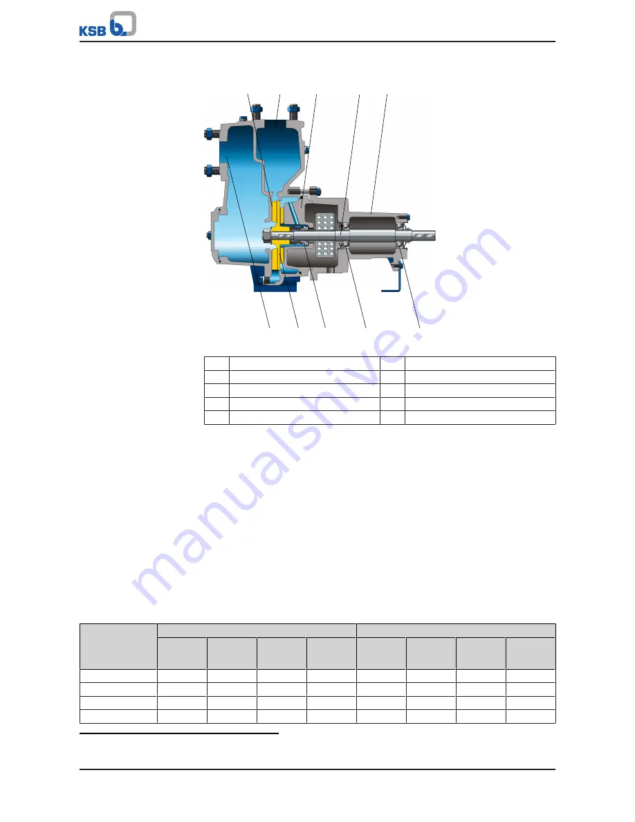
Fig. 5:
Sectional drawing
1
Clearance gap
2
Discharge nozzle
3
Casing cover
4
Shaft
5
Bearing bracket
6
Suction nozzle
7
Impeller
8
Shaft seal
9
Rolling element bearing, pump end
10
Rolling element bearing, motor end
Design
The pump is designed with an axial fluid inlet and a radial outlet. The pump section
runs in its own bearings and is connected to the motor by a shaft coupling.
Function
The fluid enters the pump axially via the suction nozzle (6) and is accelerated
outward by the rotating impeller (7). In the flow passage of the pump casing the
kinetic energy of the fluid is converted into pressure energy. The fluid is pumped to
the discharge nozzle (2), where it leaves the pump. The clearance gap (1) prevents
any fluid from flowing back from the casing to the suction nozzle. At the rear side of
the impeller, the shaft (4) enters the
hydraulic system
via the casing cover (3). The
shaft passage through the casing cover is sealed to atmosphere with a dynamic shaft
seal (8). The shaft runs in rolling element bearings (9 and 10), which are supported by
a bearing bracket (5) linked with the pump casing and/or casing cover. The filled
pump is self-priming.
Sealing
The pump is sealed by a standardised mechanical seal.
4.6 Noise characteristics
Table 7:
Surface sound pressure level L
pA
2)
Rated power
input
P
N
[kW]
Pump
Pump set
1450 rpm
[dB]
1750 rpm
[dB]
2900 rpm
[dB]
3500 rpm
[dB]
1450 rpm
[dB]
1750 rpm
[dB]
2900 rpm
[dB]
3500 rpm
[dB]
0,37
59
60
-
-
60
61
-
-
0,55
60
61
70
-
61
62
73
-
0,75
-
-
71
74
-
-
74
77
1,1
-
-
72
75
-
-
75
78
2)
Spatial average; as per ISO 3744 and EN 12639; valid for pump operation in the Q/Qopt = 0.8 - 1.1 range and for non-
cavitating operation. If noise levels are to be guaranteed: Add +3 dB for measuring and constructional tolerance.
Summary of Contents for Etaprime L
Page 1: ...Self priming Pump Etaprime L Installation Operating Manual...
Page 74: ......
Page 75: ......


