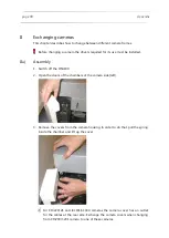
Appendix
page 91
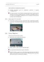
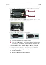
4. Remove the connections from the installed camera (image: standard camera).
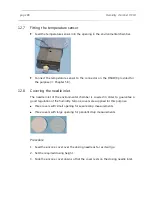
5. Loosen the screw marked in the following image using an allen wrench
(1.5 mm) and remove the camera from the guidance.
6. Unscrew the tube which is screwed onto the camera.
An increased amount of force is possibly necessary.
!
For this and the next two Steps
: Hold the camera with the opening pointing
downward so that no dust can fall onto the glass cover of the camera chip.
7. Put the protective cap on the removed camera and keep it save from dust.
8. Screw the tube onto the new camera. Insert the camera into the guidance.
9. Connect the power supply and the port for image transfer:
Connection for CF3220/21
IEEE-1394 connection for corresponding cameras
power supply
image transfer
Summary of Contents for DSA100
Page 1: ...Drop Shape Analyzer DSA100 Installation and Operation V1 45 KRÜSS GmbH Hamburg 2004 2014 ...
Page 2: ......
Page 115: ......

