page 94
Appendix
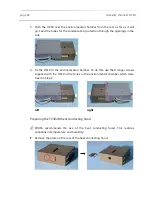
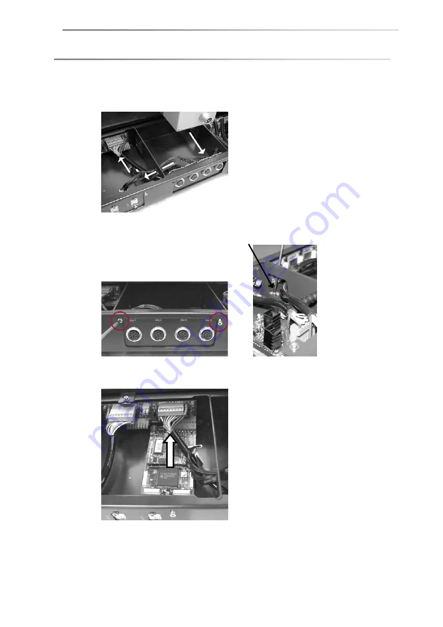
5. Place the interface board in the middle compartment, lead the connecting
cables through the gap to the compartment on the left-hand side. Use the
right-hand connection to plug the board.
6. Fix the plate with the axes connections with two screws each at the rear side
and the inside of the compartment.
7. Press the interface board to the stop into the free socket on the lower right
(seen from the rear side).
!
Take care that the whole width of the socket is used for the board so that all
poles are occupied. If the board is not properly connected it can be
destroyed when switching on the DSA100.
Summary of Contents for DSA100
Page 1: ...Drop Shape Analyzer DSA100 Installation and Operation V1 45 KRÜSS GmbH Hamburg 2004 2014 ...
Page 2: ......
Page 115: ......

