background image

13

Krowne Metal Corporation


|

 100 Haul Road 

|

 Wayne, NJ 07470

Phone: (800) 631-0442 

|

 Fax: (973) 872-1129 

|

 www.krowne.com

NOTE:


The chemical dispensing pump speeds are not set at the factory and variations in the 


type of chemicals supplied by the chemical supplier always require that the supplier 


make final adjustments for the products supplied.


1. 

Adjustment screws are provided for the dispensing pumps and for the wash tank fill. 


They are located on the right-side of the glasswasher behind the lower front access panel.

2. 

Make sure the chemical containers are full and the 


pick-up tubes are in the proper containers.

3. 

Turn the glasswasher power switch ON. 


The switch will illuminate and the glasswasher 


will fill with water.

4. 

The chemical supplier should run a normal glasswasher 


cycle and test detergent and rinse-aid concentrations 


according to the chemical supplier's instructions.

CAUTION:


Excessive pressure to the potentiometers when adjusting can result 


in bent or broken adjusting screws.


5. 

Each dispensing pump has a clearly marked 


adjustment screw.  Turn the screw CW to increase


the time of the dispensing pump and CCW to 


reduce the dispensing pump time.

6. 

The Fill adjustment screw will provide a small 


change in the tank water level.  If a large adjustment


is needed, then check the incoming water pressure 


making sure the fill hose is not kinked. If the above items


are okay then the size of the incoming water supply


should be evaluated.


7. 

Detergent, rinse-aid and sanitizer are used.


5.25% sodium hypochlorite (chlorine beach) must be used 


as a sanitizing agent to provide a minimum concentration 


of 50 ppm in the final rinse.  The 50 ppm concentration must 


be checked using chlorine test strips to make sure that the 


proper concentration is maintained. 

Initial Start-up

Chemical Dispensing Pumps

Turning the chemical dispenser 

adjusting Screws increase or 

decrease the chemical dispensed.

Proper Water Level in the Wash Tank.

Chemical Dispensing Pump Speed and Tank Fill Adjustments

Summary of Contents for GWD-24

Page 1: ... INSTRUCTION MANUAL Krowne Metal Corporation 100 Haul Rd Wayne NJ 07470 Toll Free 800 631 0442 Fax 973 872 1129 sales krowne com www krowne com www facebook com KrowneMetal www twitter com KrowneMetal MODEL GWD 24 Rev 12 2011 No GWD 1 00 Printed in the USA SERIAL NO ...

Page 2: ... ______________________ Parts Distributor ________________________________ Tel ______________________ ATTENTION The model no serial no voltage Hz and phase are needed to identify your machine and to answer questions The machine data plate is located on the lower front panel Please have this information ready if you call for service assistance SERVICE CONTACT INFORMATION Krowne Metal Corporation 10...

Page 3: ... ADDRESS _____________________ CITY STATE _______________ ZIP __________ DEALER NAME ________________________ CITY STATE ___________________ INSTALLATION COMPANY __________________________________________________ ADDRESS ______________________________________________________________ PHONE NO _____________________________________________________________ CONTACT _____________________________________...

Page 4: ...djustment of clutches f Opening or closing of utility supply valves or switching of electrical supply current g Cleaning of valves strainers screens nozzles or spray pipes h Performance of regular maintenance and cleaning as outlined in operator s guide i Damages resulting from water conditions accidents alterations improper use abuse tampering improper installation or failure to follow maintenanc...

Page 5: ...llation 7 Electrical Connections 7 Water Connection 8 Drain Connection 9 Initial Start up 10 Chemical Dispensing Pumps 11 Operation 14 Normal Wash Mode 14 Drain Mode 15 Cleaning and Maintenance 16 Cleaning 16 De liming 19 Maintenance 20 Troubleshooting 21 Service Replacement Parts 23 Electrical Schematics 46 Timer Charts 47 Table of Contents ...

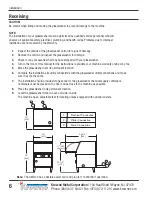
Page 6: ...the glasswasher near its permanent location 6 Compare the installation site utility connections with the glasswasher utility connections and make sure they are the same 7 The installation should provide storage space for the glasswasher chemical supply containers Containers must be placed on the floor and as close to the machine as possible 8 Place the glasswasher in its permanent location 9 Level...

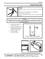
Page 7: ... the junction box located on the front right side of the machine behind the lower front access panel 3 This model requires a 115VAC 15A receptacle L1 L2 115VAC 15A 4 ft power cord w plug supplied DET SANI PRIME START TEMPERATURE ON I O POWER OFF DRAIN R A The power cord is prewired to the junction box located at the lower right side of the machine behind the lower front access panel WARNING Electr...

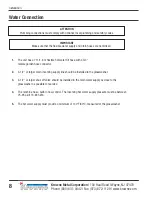
Page 8: ...f valve should be installed in the main water supply as close to the glasswasher as possible for service 4 The machine has a built in flow control The incoming hot water supply pressure must be between 25 95 psi 173 655 kPa 5 The hot water supply must provide a minimum of 140 F 60 C measured at the glasswasher Installation ATTENTION Plumbing connections must comply with national local plumbing and...

Page 9: ...TAINING CLAMP DO NOT KINK STRETCH OR LENGTHEN THE DRAIN HOSE 4 Install the drain hose to a WYE drain fitting Connection to a TEE fitting will prevent the glasswasher from draining completely 5 The maximum drain flow is 15 US gpm 12 5 Imp gpm 57 Lpm 6 Make sure the drain hose does not kink Kinks will prevent the glasswasher from draining completely and the glasswasher will overflow out the front do...

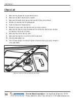
Page 10: ... not kinked 4 Remove any protective film from glasswasher 5 Check the interior for foreign material 6 Remove the scrap screen and check the sump for foreign material 7 Make sure the chemical supply containers are full and that the chemical pick up tubes are installed in the proper containers 8 Make sure the scrap screen is in place 9 Make sure the spray arm is in place and that it spins freely 10 ...

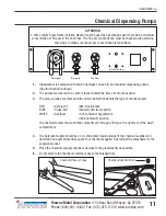
Page 11: ...wer front access panel 3 The pick up tubes are marked with colored labels that identify the type of chemical used RED Detergent Non chlorinated BLUE Rinse Aid Consult chemical supplier WHITE Sanitizer 5 25 Sodium hypochlorite chlorine bleach solution The chemicals enter the wash tank compartment through a fitting on the right rear of the wash compartment 4 The detergent supply should be a non chlo...

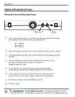
Page 12: ...sher door then push and hold the first prime push button UP to the DET position until detergent enters the wash tank compartment Release the PRIME push button 5 Push and hold the prime push button DOWN to the SAN position until sanitizer is observed entering the wash tank compartment Release the Prime push button 6 Push and hold the second prime push button UP to the R A position until rinse aid i...

Page 13: ...essive pressure to the potentiometers when adjusting can result in bent or broken adjusting screws 5 Each dispensing pump has a clearly marked adjustment screw Turn the screw CW to increase the time of the dispensing pump and CCW to reduce the dispensing pump time 6 The Fill adjustment screw will provide a small change in the tank water level If a large adjustment is needed then check the incoming...

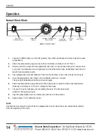
Page 14: ...nd The cycle light illuminates and the wash cycle begins 6 Check the temperature gauge during the final rinse cycle to ensure the final rinse temperature indicates a minimum of 140 F 60 C during the final rinse 7 The green in cycle light goes out completing the cycle The final rinse water is held for the next wash cycle 8 Open the glasswasher door and remove the dish rack of clean wares 9 Repeat s...

Page 15: ...washer starts and the green cycle light illuminates 6 Check the temperature gauge to confirm that it displays the correct incoming hot water temperature This may take several minutes for the wash tank to reach temperature 7 When the glasswasher stops push the POWER switch down to the OFF DRAIN position 8 After a 4 second pause the green cycle light will illuminate the machine will drain fill with ...

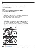
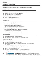
Page 16: ...y 8 hours of Operation 1 Remove the scrap screen and flush with clean water Be sure to backflush the screen 2 Inspect the sump and pump intake screen and clean as required 3 Reassemble the machine and return to normal operation Daily End of the Day 1 Push the POWER switch to the OFF DRAIN position and close the door to drain the tank The green in cycle light will illuminate indicating the machine ...

Page 17: ... scrap screen by rinsing with clean water Be sure to backflush the screen Do not strike the screen on hard surfaces 5 Inspect the sump and remove any foreign material 6 Clean the pump intake screen The pump intake screen is not removable 7 Reinstall the scrap screen Cleaning Sump Pump Intake Screen continued on next page Cleaning ...

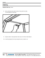
Page 18: ... Daily End of the Day continued Cleaning Cleaning 8 Using a small paperclip clean the nozzles in the upper rinse piping The rinse piping is not removable 9 Wipe the exterior of the glasswasher clean using a soft cloth and mild detergent 10 Leave the glasswasher door open overnight to allow the inside to dry ...

Page 19: ...s and hold the prime switch UP in the DET position for 2 minutes to flush the detergent from the supply tubing Release the switch 6 Press and hold the prime switch DOWN in the SAN position for 4 minutes to flush the sanitizer from the supply tubing Release the switch 7 Press and hold the prime switch UP in the R A position for 4 minutes to flush the rinse aid from the supply tubing Release the swi...

Page 20: ...lime deposits from the wash tank heating element 7 Inspect the scrap screen and replace it if damaged 8 Check the spray arm and replace or repair if damaged Monthly Maintenance 1 Perform the Daily and Weekly Maintenance listed above 2 Clean the chemical dispenser pick up tubing by flushing with hot water To clean the pick up tubing 1 Remove the pick up tubes from their containers 2 Place each tube...

Page 21: ...Supply tubing damaged Supply tubing kinked Pick up tube clogged or defective Timer board defective Refill chemical container Replace tubing Straighten tubing Clean replace tube Test replace timer board Low water pressure pumped from spray arms Clogged scrap screen Clogged spray arms Clogged pump intake screen Clean scrap screen Clean spray arms Clean sump and pump intake screen Poor wash results W...

Page 22: ...22 Krowne Metal Corporation 100 Haul Road Wayne NJ 07470 Phone 800 631 0442 Fax 973 872 1129 www krowne com This Page Intentionally Left Blank Blank Page ...

Page 23: ...ical Panel and Timer Board Assembly 26 Control Panel Assembly 28 Wash Rinse and Drain Assemblies 30 Wash Tank Heater and Scrap Screen 32 Drain Manifold and Fill Solenoid Valve Assembly 34 Fill Chute and Rear Piping Assembly 36 Panel Assembly 38 Door Assembly 40 Chemical Dispensing Pumps 42 Dish Racks 44 Electrical Schematic 46 Timer Chart 47 Service Replacement Parts ...

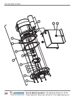
Page 24: ...24 Krowne Metal Corporation 100 Haul Road Wayne NJ 07470 Phone 800 631 0442 Fax 973 872 1129 www krowne com Wash Pump Motor Assembly 1 2 6 8 11 9 13 14 3 4 5 7 12 10 ...

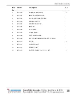
Page 25: ... 1 3 GW 1002 NUT M6 LEFT HAND THREADS 1 4 GW 1003 WASHER LOCK 1 4 1 5 GW 1004 WASHER PLAIN 17 64 1 6 GW 1005 IMPELLER 1 7 GW 1006 SEAL PUMP 1 8 GW 1007 GASKET PUMP 1 9 GW 1008 PLATE PUMP BACKING 1 10 GW 1009 MOTOR PUMP ASSEMBLY COMPLETE 115V 60 1 1 11 GW 1010 NUT M4 9 12 GW 1011 CAPACITOR 40μF 1 13 GW 1012 BRACKET PUMP 1 14 GW 1013 BOLT HEX FLANGE 1 4 20 X 3 8 SST 2 Item No Part No Description Qty...

Page 26: ...e Metal Corporation 100 Haul Road Wayne NJ 07470 Phone 800 631 0442 Fax 973 872 1129 www krowne com Electrical Panel and Timer Board Assembly 1 2 3 4 6 7 4 8 13 15 10 14 12 16 17 6 19 18 10 12 13 14 15 4 9 5 4 ...

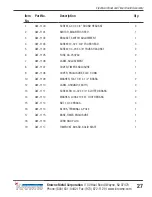
Page 27: ...W 1 4 20 X 3 8 TRUSS HEAD SST 2 6 GW 1105 FUSE 4A 250VAC 2 7 GW 1106 LABEL ADJUSTMENT 1 8 GW 1107 COVER TIMER ENCLOSURE 1 9 GW 1108 COVER ENCLOSURE ELEC CONN 1 10 GW 1109 WASHER FLAT 1 8 X 1 2 BRASS 2 12 GW 1110 LABEL GROUND EARTH 2 13 GW 1111 SCREW RH 10 32 X 3 4 SLOTTED BRASS 2 14 GW 1112 WASHER LOCK 10 EXT TOOTH BRASS 4 15 GW 1113 NUT 10 32 BRASS 4 16 GW 1114 BLOCK TERMINAL 4 POLE 1 17 GW 1115 ...

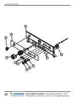
Page 28: ...28 Krowne Metal Corporation 100 Haul Road Wayne NJ 07470 Phone 800 631 0442 Fax 973 872 1129 www krowne com Control Panel Assembly 1 11 7 6 4 5 8 9 10 2 3 ...

Page 29: ...L FACIA 1 3 GW 1202 SWITCH ROCKER DPST 125V NEON 1 4 GW 1203 THERMOMETER 2 DIAL 1 5 GW 1204 SWITCH ROCKER RND SPDT MOMENTARY 2 6 GW 1205 LIGHT INDICATOR GREEN LED 2VDC 1 7 GW 1206 BUTTON SWITCH GREEN 1 8 GW 1207 HOUSING SWITCH 1 9 GW 1208 CONTACT MOMENTARY N O 1 10 GW 1209 SCREW NIBS RH 6 32 X 3 16 PHIL SST 2 11 GW 1210 THERMOSTAT WASH TANK 1 Item No Part No Description Qty ...

Page 30: ...one 800 631 0442 Fax 973 872 1129 www krowne com Wash Rinse and Drain Assemblies See illustration on pg 58 59 for detailed view See illustration on pg 58 59 for detailed view 6 1 2 26 3 4 5 14 20 25 17 17 23 24 18 19 15 16 17 14 7 8 9 10 11 12 13 11 22 21 17 23 ...

Page 31: ... PLASTIC 1 11 GW 1013 BOLT HEX FLANGE 1 4 20 X 3 8 SST 4 12 GW 1311 CLAMP VALVE 1 13 GW 1312 BRACKET VALVE 1 14 GW 1313 CLAMP HOSE 1 1 2 GEAR TYPE SST 4 15 GW 1314 HOSE PUMP SUCTION 1 16 GW 1315 HOSE 5 8 ID X 1 OD BRAIDED A R 17 GW 1316 CLAMP GEAR MIN 5 16 MAX 7 8 SST 5 18 GW 1317 HOSE 1 19 GW 1318 CLAMP HOSE 1 13 16 2 3 4 MAX SST 1 20 GW 1319 HOSE PUMP DISCHARGE 1 21 GW 1320 HOSE 1 2 X 7 FT W FEM...

Page 32: ...32 Krowne Metal Corporation 100 Haul Road Wayne NJ 07470 Phone 800 631 0442 Fax 973 872 1129 www krowne com Wash Tank Heater and Scrap Screen 1 9 11 12 2 2 7 3 4 5 5 4 3 8 2 6 ...

Page 33: ...AC 750W C W NUT GASKET 1 3 GW 1402 ADAPTER THERMOMETER 2 4 GW 1403 O RING 2 5 GW 1404 NUT LOCK 1 2 NICKLE PLATED 2 6 GW 1405 THERMOSTAT FIXED HIGH LIMIT 212ºF 1 7 GW 1406 NUT GRIP 6 32 W NYLON INSERT SST 2 8 GW 1407 BUSHING THERMOSTAT USE WITH ITEM 9 1 9 GW 1210 THERMOSTAT WASH TANK 1 11 GW 1409 ADAPTER 1 12 GW 1203 THERMOMETER 2 DIAL C W 7 FT CAPILLARY 1 Item No Part No Description Qty ...

Page 34: ...ne Metal Corporation 100 Haul Road Wayne NJ 07470 Phone 800 631 0442 Fax 973 872 1129 www krowne com Drain Manifold and Fill Solinoid Valve Assembly 1 2 3 13 12 14 15 20 22 21 19 18 17 23 7 4 6 5 11 10 9 8 16 ...

Page 35: ...W 1506 O RING DRAIN SHAFT 1 8 GW 1507 SCREW TRUSS SLOT 10 32 X 3 8 SST 2 9 GW 1508 GASKET DRAIN 1 10 GW 1509 FLAP DRAIN 1 11 GW 1510 NUT GRIP 10 32 SST 1 12 GW 1511 SCREW 8 32 X 1 2 SLOT RH SST 3 13 GW 1512 WASHER SPLIT LOCK 8 3 14 GW 1513 COIL 115V 60 1 10W 1 15 GW 1514 GUIDE 1 16 GW 1515 KIT REBUILD VALVE A R 17 GW 1516 VALVE WATER INLET 115VAC 60 1 1 Includes Items 12 21 18 GW 1517 WASHER FLOW ...

Page 36: ...e NJ 07470 Phone 800 631 0442 Fax 973 872 1129 www krowne com Fill Chute and Rear Piping Assembly From Detergent Pump From Rinse Aid Pump From Sanitizer Pump From Manifold From Manifold To Drain From Fill Valve 2 1 3 4 13 14 12 7 4 8 6 5 10 4 9 11 ...

Page 37: ... GW 1603 NUT HEX 10 32 SST 6 5 GW 1604 HOSE 1 8 ID X 1 4 OD RINSE AID SANITIZER A R 6 GW 1605 HOSE 1 4 ID X 3 8 OD DETERGENT A R 7 GW 1606 TIE PLATE TP 2 1 8 GW 1607 TIE NYLON 4 1 9 GW 1608 CLAMP 1 PLATED CABLE STRAP 2 10 GW 1315 HOSE 5 8 ID X 1 OD PVC BRAIDED A R 11 GW 1322 HOSE RUBBER 1 2 ID X 84 OD A R 12 GW 1316 CLAMP GEAR MIN 5 16 MAX 7 8 SST 1 13 GW 1612 O RING 1 14 GW 1613 LOCKNUT 1 2 NPT 1...

Page 38: ...38 Krowne Metal Corporation 100 Haul Road Wayne NJ 07470 Phone 800 631 0442 Fax 973 872 1129 www krowne com Panel Assembly 16 15 6 16 14 13 1 2 3 5 9 12 11 10 7 4 ForLowTemp ...

Page 39: ...1 4 20 SST 4 5 GW 1704 RAIL TRAY RH 1 6 GW 1705 RAIL TRAY LH 1 7 GW 1706 LEG NP W SST HEX FOOT 4 9 GW 1707 SCREW 1 4 20 X 5 8 TRUSS PHIL SST 2 10 GW 1708 PANEL LOWER FRONT 1 11 GW 1709 LABEL ENERGY STAR 1 1 12 GW 1104 SCREW 1 4 20 X 3 8 TRUSS HEAD SST 2 13 GW 1711 GASKET DOOR 1 8 X 5 8 X 21 5 LG 1 14 GW 1712 BRACKET RETAINING LS UPPER WASHARM 1 15 GW 1713 BRACKET RETAINING RS UPPER WASHARM 1 16 GW...

Page 40: ...40 Krowne Metal Corporation 100 Haul Road Wayne NJ 07470 Phone 800 631 0442 Fax 973 872 1129 www krowne com Door Assembly 7 8 1 5 5 4 3 5 6 2 ...

Page 41: ...800 DOOR WELDED ASSY 1 2 GW 1801 NUT COUPLING 1 4 20 X 7 8 sst 1 3 GW 1802 BRACKET HINGE TANK LS 1 4 GW 1013 BOLT HEX HEAD FLANGE 1 4 20 X 3 8 SST 2 5 GW 1104 SCREW 1 4 20 X 3 8 TRUSS HEAD SST 4 6 GW 1805 BRACKET HINGE TANK RS 1 7 GW 1806 HOLDER MAGNET 1 8 GW 1807 SCREW 4 40 X 1 4 ROUND HEAD SST 2 Item No Part No Description Qty ...

Page 42: ...Phone 800 631 0442 Fax 973 872 1129 www krowne com Chemical Dispensing Pumps To Injection Point To Injection Point To Injection Point 17 1 12 10 18 6 11 17 17 17 14 13 16 15 9 8 5 3 7 6 6 2 2 4 Check squeeze tube Item 3 for wear every 6 months Yellow Rollers ...

Page 43: ...W 1904 CLAMP HOSE 1 6 GW 1608 TIE CABLE 4 8 7 GW 1906 ELBOW 1 4 HOSE BARB 2 8 GW 1605 HOSE 1 4 ID X 3 8 OD PVC A R 9 GW 1908 LABEL DETERGENT 1 10 GW 1909 ROTOR ASSEMBLY 2 11 GW 1910 SCREW 6 32 X 7 8 PAN HD PHIL SST 4 12 GW 1911 LABEL RINSE AID 1 13 GW 1912 LABEL SANITIZER 1 14 GW 1913 TUBE 1 2 ID X 11 7 8 LG STIFFENER 2 15 GW 1914 TUBING 1 8 OD X 1 16 ID RINSE AID A R 16 GW 1604 HOSE 1 8 ID X 1 4 ...

Page 44: ...44 Krowne Metal Corporation 100 Haul Road Wayne NJ 07470 Phone 800 631 0442 Fax 973 872 1129 www krowne com Dish Racks Line Strainer PRV 1 2 ...

Page 45: ...poration 100 Haul Road Wayne NJ 07470 Phone 800 631 0442 Fax 973 872 1129 www krowne com Dish Racks Line Strainer PRV 1 GW 2000 RACK SILVERWARE FLAT BOTTOM 1 2 GW 2001 RACK PLATE TRAY PEG 1 Item No Part No Description Qty ...

Page 46: ...T WP SS CPS CL 1HTR POL HC1 DEP BOOSTER SAFETY THERMOSTAT EXTENDED WASH SWITCH SANITIZER PUMP SP EWS BS POWER ON SWITCH RINSE AID PUMP TANK HEAT SAFETY THERMOSTAT TANK HEAT THERMOSTAT BOOSTER THERMOSTAT TT TS BT RAP PS EXTENDED WASH LIGHT WASH TANK HEATER WHTR EWL PROTECTION 15 AMPS MINIMUM CIRCUIT AMPACITY MAXIMUM OVERCURRENT 15 AMPS LOW VOLTAGE SECTION 2 AND 5 VDC CL DVC DIAGRAM STATE END OF CYC...

Page 47: ...0 SEC 20 SEC 12 SEC 55 SEC MAXIMUM DENOTES ADJUSTABLE TIME 115 45 TOLERANCE DECIMAL ANGLE SCALE FORMING DIMENSIONS ARE FROM BRAKELINE TO BRAKELINE UNLESS OTHERWISE NOTED A B C D E F G H J ISSUED DR CH RTG HOLE DIMENSIONS 1 2 WASH CYCLE TIMING CHARTS Timer Bd Potentiometers TIME SEC 1 WASH PUMP 3 FILL VALVE 2 DRAIN VALVE N G C 10 0 20 TIMING CHART FOR FILL AND DUMP DRAIN CYCLE ACTIVATED 4 SEC AFTER...

Page 48: ......

Reviews: