Supplementary Documentation
Page 6 of 44
IFC090, IFC090 i with FF
Installation and Operation
IFC090 FF 01/2005
KROHNE Messtechnik GmbH & Co. KG · Ludwig-Krohne-Str. 5
D-47058 Duisburg
Tel.: 0203-301 309
Fax: 0203-301389 · E-mail: [email protected]
2.4
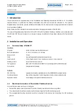
Shielding and Grounding
For optimum electromagnetic compatibility of systems it is extremely important that the system components,
and particularly the bus cables connecting the components, are shielded and that such shields - if possible -
form an unbroken cover.
Hence, it follows that, for use in non-hazardous duty systems, the cable shield should be grounded as often as
possible.
In “Ex“ systems an adequate equipotential bonding in the hazardous and non-hazardous location along the
entire fieldbus installation is strongly recommended. Multiple grounding of the shield is of advantage.
Note: The use of twisted and shielded cables is strongly recommended, otherwise EMC protection of the IFC
090 cannot be assured.
2.5
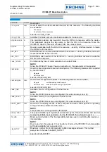
IFC090 Menu Settings for Foundation Fieldbus
(see also Section 4 in the Installation and Operating Instructions for the IFC090)
The following settings need to be made for operation of the IFC 090 on a Foundation Fieldbus network. Note
that the address can be set by the service “set slave address” as well.
Function (Fct.) Description
3.9 COM
Select function for the communication port
♦
OFF
♦
HART
♦
PROFI PA *
•
Note: * indicates Foundation Fieldbus Communication when selected
2.6
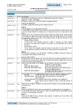
Foundation Fieldbus Functional Blocks
The IFC090 supports the H1 Foundation Fieldbus Communication Standard FF-003-2.2-1-1, Version 1.4.
Additionally, all relevant parameters in the device are offered via the FF interface. The IFC 090 defines the
following functional blocks:
•
Three Function Blocks (FB): One Analog Input-FB for flow and two integrator-FBs for integration.
Reset function is possible.
•
One Transducer Block for electromagnetic flow measurement.
•
One standard Resource Block.

