Supplementary Documentation
Page 34 of 44
IFC090, IFC090 i with FF
IFC090-FF Configuration
IFC090 FF 01/2005
KROHNE Messtechnik GmbH & Co. KG · Ludwig-Krohne-Str. 5
D-47058 Duisburg
Tel.: 0203-301 309
Fax: 0203-301389 · E-mail: [email protected]
To avoid alarm flicker if the OUT value oscillates around one of these alarm limits, the user is able to configure a
hysteresis in parameter ALARM_HYS, as value in percent of the OUT_SCALE span.
5.4 Integrator
Blocks
Configuration
The two Integrator Blocks of the IFC090-FF are working very similar. The reason to support two Integrator
Blocks is, that the IFC090-FF is capable of measuring forward (positive) and reverse (negative) flow at the same
time. Both Integrators were intended to totalize the forward flow (Integrator 1 (Flow(+)-Totalizer) on the one
hand, and the reverse flow (Integrator 2 (Flow(-)Totalizer) on the other.
The configuration of these blocks is almost the same, unless stated differently.
5.4.1
Integrator Block Mode Handling
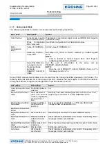
By selecting the operation mode in parameter MODE_BLK, the operator is able to control the activities of the
Integrator block. The following lists the available modes and meanings:
Integrator Block MODE_BLK
Description
Automatic (AUTO)
The Analog Input block performs its functional computations in
accordance to its configuration automatically. Measurement
deliverance is active.
Manual
(Man)
The block doesn’t perform an automatic deliverance of valid
measurement values, but freezes the measurement processing to the
last value obtained in Automatic mode. The OUT status limit switches
to ‘Constant’. In this mode it is possible to write to the OUT value an
arbitrary value to test blocks that use this OUT value as input.
Out of Service (OOS)
The block stops its operation and freezes its measurement value to
the last one obtained in Automatic mode. The OUT status switches to
BAD:OutOfService:NotLimited.
5.4.2
Integration Input – Rate or Accumulated Pulses
Each Integrator consists of two input parameter IN_1 and IN_2, which can be used at the same time (e.g. for the
totalization of two different flow meters). Both IN_1 and IN_2 can be configured as rate input (e.g. m3/s, kg/min,
etc.) or as continuous accumulation of pulses.
By default both inputs are configured as rate, but can be configured separately as continuous accumulation of
pulses by setting the options ‘Input 1 accumulate’ (for IN_1), or ‘Input 2 accumulate’ (for IN_2), respectively in
parameter INTEG_OPTS to true.
5.4.3
Adaptation of Integrator Inputs
The integration process is a function that maps a quantity unit per time unit (in case of a rate input), or a number
of pulses (in case of continuous accumulation) to a total quantity unit. For this reason, it is necessary to adapt
the inputs to the needs of the integration process. For the two possible integration types, different adaptations
are required:
Rate input


