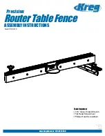
Precision Router Table Fence Assembly
5.
Step 9
Insert six ¼-20 x 1” Phillips Flat Head Machine Screws (#22) through the
pre-drilled/countersunk holes in the two separate Fence Faces and barely
thread the six corresponding ¼” Jam Nuts (#27) onto the Screws. Be sure
to use the thinner Jam Nuts and not the thicker Hex Nuts. The Hex Nuts
are too large to slide into the t-slot of the Fence. With the bolts and nuts
secured onto the Fence Faces, take each Face and slide it onto the front
t-slot of the Fence, center, and tighten each bolt down securely
Step 8
Flip the Large Fence over. On the underside of the Fence you will fi nd two
slots running down the length of the extrusion. Insert the eight Trak Bumpers
(#34), approximately 4.5” and 12” from each end, as shown in the image.
Correctly installed Trak Bumpers will reduce friction and ensure the fence
glides smoothly across the table top.
12”
4.5”
Step 12
On the other end of the fence, slide the head of a ¼-20 x ¾” Hex Bolt (#31)
into the T-Slot. Slide the slotted end of the Right Angle Bracket (#12) around
the Hex Bolt and fasten with one ¼” Fender Washer (#33) and one ¼” Hex
Nut. Before tightening the nut, align the Right Angle Bracket over the 6” slot
on the left side of the Kreg Router Table Top. Place the Brass T-Nut (#30)
through the slot from the underside of the Router Table Top and attach the
Extension Knob Asembly (#13) by putting it through the Right Angle Bracket
and threading it into the Brass T-Nut. Once the right angle bracket is correctly
positioned, tighten the hex nut to secure it into place.
Step 10
Slide the two ¼-20 x 2-1/4” Hex Bolts (#26) into the T-slot on the back of
the Large Fence (#4) next to the Fence Mount (#3). Adjust the position of
the two bolts so that they fi t into the two slots on top of the Fence Mount
and move the fence so its centered on the router bit opening. Lock the
fence into place using two ¼” Brass Washers (#17). and two T-Knobs
(#16).
Step 11
With the fence centered on the bit opening, use a rule to bring the fence
perfectly parallel to the miter slot. Tighten the four ¼-20 3/8” Phillips Pan
Head Machine Screws (#18) that you installed earlier in Step 5, to lock the
fence into position.


