background image

Safety Guidelines

1.

Locate the Table Mount (#5) and position it underneath the far right hand 
corner of your Kreg Precision Router Table Top.  Using the four 1” Coarse 
Thread Screws (#28) and the pre-drilled holes in the Table Top, secure the 
Table Mount fl ush with the back and right side edges of the Table Top. 

Note:  If you are using a homemade or other type of router table top you will 
not have pre-drilled holes for this step.  When you screw in the Coarse Thread 
Screws, be extra sure that the Table Mount is perfectly fl ush with the back and 
right side edges of the table top before securing.  Also be sure that the hardware 
is not so long that it will puncture your top surface when completely driven.  You 
may need to purchase shorter hardware if this is a potential problem.  

Step 1

Insert the four ¼-20” x ¾” Hex Bolts (#31) into the holes (not slots) on the 
side of the Table Mount (#5) and attach using four ¼” Brass Washers (#17) 
and four ¼-20 Hex Nuts (#23).  Be sure to use the thicker Hex Nuts and not 
the thinner Jam Nuts.  The bolts should hang loosely at this point.  Do not 
tighten down.  

Note:  If you are using a homemade or other type of router table top you will 
use the slots in the Table Mount instead of the holes.  This will allow you to 
adjust for the thickness of your Table Top later on. 

Step 2

·   Woodworking machines are dangerous, and can cause personal injury if not
 used 

properly.

·   Read safety instructions and operating instructions for your machine completely, 
  before using products.  Using this system before understanding its safe and
  proper use could result in serious injury to the operator.  

·   Failure to follow these rules may result in serious personal injury.

·   For your own safety, read instruction manual before operating the tool.  Learn the 
  tools application and limitations as well as the specifi c hazards distinctive to it.

·   Keep all guards and safety devices in proper place while using these products. 

·   Always wear safety glasses.

·   Keep hands well away from the rotating bit when operating machine.

·   Avoid awkward hand positions, where a sudden slip could cause contact with the 
  rotating bit.  

·   This system was designed for certain applications only.  Kreg strongly recommends 
  that this system NOT be modifi ed and/or used for any application other than 
  for which it was designed.  If you have any questions relative to its application, 
  DO NOT use the tool until you have written, phoned, or e-mailed Kreg Tool and 
  have been advised accordingly.

·   Be aware of kickbacks.  Kickbacks occur when the workpiece binds-up while being 
  routed, causing it to twist, jump, and possibly become airborne.  To avoid kickbacks
  (and potential injury) always use sharp bits, keep the machine aligned and  
  maintained properly, and adequately secure/support the workpiece.

·   Turn machine off before adjusting.  Never adjust the fence, plate level, reducing rings, 
  or any other part of the tool while the machine is running.

·   Wait for the machine to stop.  Make sure the router comes to a complete stop before 
  adjusting the workpiece or workpiece-angle.

·   Ground electric machines.  If your machine is equipped with a three-prong plug, it
  should be plugged into a three-hole electrical receptacle only.  If the proper
  outlet is not available, have one installed by a qualifi ed electrician before use. 
  Never remove the third prong, and never modify the provided plug in any way.  

·   Don’t operate in a dangerous or unclean environment.  Don’t use power tools in
  damp or wet locations, or expose them to rain.  Keep work area well-lit,
  un-cluttered, and clean.

·   Keep children and visitors away.  All children and visitors should be kept a safe distance 
  from the work area, and should not operate the tool under any condition.

·   Make your workshop “child-proof”.  Use padlocks, master switches, or any other means 
  necessary to make your work area safe for children.  

·   Use the right tool.  Never ‘force’ the tool to do work for which it was not intended.  If used 
  properly, the tool will produce better results in less time, under safer conditions.

·   Wear proper apparel.  No loose clothing, gloves, neckties, rings, bracelets, or any other 
  jewelry that could possibly get caught in moving parts.  Non-slip footwear is highly 
  recommended, as is protective hair covering.  Remember to always use safety glasses, 
 specifi cally designed as safety wear.  

·   Secure the workpiece.  Use clamps or a vise to hold work when it is practical and safe.   

  Using the proper tool may allow you to free both hands for tool operation.  Also, be sure 
  to never overreach.  

·   Secure your tools.  In the event of the machine tipping or sliding, it is always    
  recommended to secure your tools to the machine during use.    

·   Keep the proper footing and balance.  Ensure that you are in no danger of slipping or 
  sliding once you turn the machine on.  Once again, non-slip footwear is highly 
 recommended.

·   Maintain tools in top condition.  Keep tools sharp, clean, and properly maintained for the 
  highest quality and safest performance.  Remember to properly follow all lubrication and 
  accessory maintenance practices, as detailed in this Instruction Manual.

·   Disconnect tool before servicing.  When changing accessories such as bits, clamps, etc., 
  making any sort of physical assessment of the tool, or when motor is being mounted/
  connected, remember to disconnect the machine from its power source.  This will reduce 
  the possibility of accidentally engaging the machine.

·   Check for damaged parts.  Before use of the tool, a careful assessment of all guards and  
  other parts should be made to ensure that it will operate properly,  and perform as 
  intended.  Check for alignment of moving parts, binding of moving parts, breakage of 
  parts, mounting, and any other conditions that may affect its operation.  A guard or other 
  part that is damaged should be properly repaired or replaced as soon as possible, 
  preceding any additional use.  Do not use the tool if you are not qualifi ed to make these 
  sorts of assessments.

·   Never leave a running machine unattended.  Always turn the machine’s power “OFF” 
  after operation.  Do not leave the tool until it comes to a complete stop.

·   Drugs, alcohol, medication warning.  Do not operate tool while under the infl uence of 
  drugs, alcohol, or any medications.

·  

WARNING:

 This product contains one or more chemicals known to the State

  of California to cause cancer and birth defects or other reproductive harm.
 

Wash hands after handling

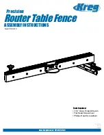
Precision Router Table Fence Assembly

Summary of Contents for PRS1010

Page 1: ...Tools Required 7 16 Open Ended Wrench Flat Head Screwdriver Phillips Head Screwdriver RouterTableFence Precision ASSEMBLY INSTRUCTIONS Item PRS1010 www kregtool com 800 447 8638 RT10142 Rev C 5 2010 ...

Page 2: ...with a three prong plug it should be plugged into a three hole electrical receptacle only If the proper outlet is not available have one installed by a qualified electrician before use Never remove the third prong and never modify the provided plug in any way Don t operate in a dangerous or unclean environment Don t use power tools in damp or wet locations or expose them to rain Keep work area wel...

Page 3: ... play out of the fence and allows for more fluid motion of the Mounting Rail Make adjustments as necessary Step 4 Locate the Fence Mount 3 and align the four holes with the corresponding holes on the Clamp Block 2 Secure the two together using the four Brass Washers 17 and four 20 x 3 8 Phillips Pan Head Machine Screws 18 without tightening completely You will need to adjust the positioning of the...

Page 4: ...Precision Router Table Fence Parts Explosion 3 K M L O N D J B C A E F H I G F G O ...

Page 5: ...OB DK1313 4 17 1 4 BRASS WASHER DK1504 12 18 1 4 20 X 3 8 PAN HEAD MS RT10137 8 19 KNURLED THUMB SCREW RT10185 1 20 10 32 X 1 4 NYLON SCREW FT4064 1 21 1 4 NYLON SNAP RIVET RT10130 8 22 1 4 20 X 1 FLAT HEAD MS RT10136 6 23 1 4 20 HEX NUT DK1510 5 24 PLASTIC SPACER WASHER RT10134 2 25 1 4 20 X 1 1 4 T BOLT FT4212 2 26 1 4 20 X 2 1 4 HEX BOLT RT10186 2 27 1 4 20 JAM NUT RT10141 6 28 1 COARSE SCREW S...

Page 6: ...e T Slot Slide the slotted end of the Right Angle Bracket 12 around the Hex Bolt and fasten with one Fender Washer 33 and one Hex Nut Before tightening the nut align the Right Angle Bracket over the 6 slot on the left side of the Kreg Router Table Top Place the Brass T Nut 30 through the slot from the underside of the Router Table Top and attach the Extension Knob Asembly 13 by putting it through ...

Page 7: ... two Plastic Spacer Washers 24 onto each T Bolt and place the Fence Guard 11 on to each T Bolt Fasten using two Brass Washers 17 and two Small T Knobs 16 Slide the Precision Lens Cursor 10 into the Mounting Rail as far as is shown and lock it into place using the 10 32 x Nylon Screw 20 This Screw can be loosened and re tightened to make any adjustments necessary to the Precision Lens Cursor Slide ...

Page 8: ...ide the rods into the corresponding deeper recesses as shown in the right photo When the rods are inserted and you have the correct depth setting re tighten the fence face to the fence To position your fence for use with a common edge bearing bit start by loosening the individual fence faces and positioning them as close as possible to the cutter without making contact with the bit Rotate the bit ...

Page 9: ...Outils nécessaires Clé à fourches de 7 16 po Tournevis à tête plate Tournevis cruciforme RouterTableFence Precision Item PRS1010 www kregtool com 800 447 8638 INSTRUCTIONS POUR L ASSEMBLAGE ...

Page 10: ...e de courant à trois alvéoles Si vous ne disposez pas d une telle prise demandez à un électricien qualifié d en installer une avant d utiliser la machine Ne retirez jamais la troisième broche et ne modifiez jamais la fiche N utilisez pas l outil dans un environnement dangereux et malpropre N utilisez pas un outil électrique dans un endroit mouillé ou humide et ne l exposez pas à la pluie Gardez l ...

Page 11: ...fixation Apportez des ajustements au besoin Étape 4 Repérez le support du guide no 3 et alignez les quatre trous aux trous correspondants sur le bloc de serrage no 2 Fixez le support et le bloc ensemble à l aide des quatre rondelles en laiton no 17 et des quatre vis à métaux cruciformes à tête cylindrique à dépouille de 1 4 po 20 UNC x 3 4 po no 18 sans les serrer complètement Vous aurez besoin d ...

Page 12: ...Liste des pièces du guide longitudinal pour table à toupie de précision 3 K M L O N D J B C A E F H I G F G O ...

Page 13: ...4 PO 20 UNC X 3 8 PO RT10137 8 19 VIS DE SERRAGE MOLETÉE RT10185 1 20 VIS EN NYLON DE 10 À 32 UNC X 1 4 PO FT4064 1 21 BOUTEROLLE EN NYLON DE 1 4 PO RT10130 8 22 VIS À MÉTAUX CRUCIFORME À TÊTE PLATE DE 1 4 PO 20 UNC X 1 PO RT10136 6 23 ÉCROU HEXAGONAL DE 1 4 PO 20 UNC DK1510 5 24 RONDELLE D ESPACEMENT EN PLASTIQUE RT10134 2 25 BOULON POUR RAINURE EN T DE de 1 4 po 20 UNC x 1 1 4 po FT4212 2 26 BOU...

Page 14: ... 12 autour du boulon à tête hexagonale et fixez le tout à l aide d une rondelle large de 1 4 po no 33 et d un écrou hexagonal de 1 4 po Avant de visser l écrou alignez le support à angle droit avec la fente de 15 24 cm située sur le côté gauche du plateau de la table à toupie Kreg Insérez l écrou pour rainure en T en laiton no 30 dans la rainure en passant par le dessous du plateau de la table à t...

Page 15: ...u guide insérez une rondelle d espacement en plastique no 24 sur chaque boulon et insérez le protecteur no 11 sur ces boulons Fixez le protecteur avec deux rondelles en laiton de 1 4 po no 17 et deux petits boutons en forme de T no 16 Glissez le curseur à lentille de précision no 10 dans la traverse de fixation aussi loin que l illustre l image et fixez le en place à l aide de la vis en nylon de 1...

Page 16: ... dans les alvéoles correspondantes plus profondes comme l illustre l image de droite Après avoir inséré les tiges et réglé la bonne profondeur revissez le guide de sortie au guide principal Pour placer le guide que vous utiliserez avec une toupie dont le bout a un bord régulier à roulement commencez par desserrer chaque face du guide et placez les le plus près possible de la lame sans qu elles tou...

Page 17: ...outerTableFence Precision Artículo PRS1010 www kregtool com 800 447 8638 Herramientas necesarias Llave española de 7 16 Destornillador de cabeza plana Destornillador Phillips INSTRUCCIONES DE ENSAMBLAJE ...

Page 18: ... en un tomacorriente de tres orificios Si no se cuenta con un enchufe adecuado pídale a un electricista calificado que instale uno antes de usar Nunca retire la tercera clavija y nunca modifique el enchufe incluido de ninguna manera No use en entornos peligrosos o sucios No utilice herramientas eléctricas en áreas húmedas o mojadas ni las exponga a la lluvia Mantenga el área de trabajo bien ilumin...

Page 19: ...ovimiento más fluido del riel de montaje Ajuste según sea necesario Paso 4 Ubique el montaje de la guía 3 y alinee los cuatro orificios con los orificios correspondientes en la abrazadera de bloque 2 Asegúrelos juntos con las cuatro arandelas de latón 17 y cuatro tornillos para metales de cabeza plana Phillips de 20 x 3 8 18 sin ajustar por completo Deberá ajustar la posición del montaje de la guí...

Page 20: ...Exposición de las piezas de la guía de la mesa para rebajadora Precision 3 K M L O N D J B C A E F H I G F G O ...

Page 21: ...0 X 3 8 RT10137 8 19 TORNILLO DE MARIPOSA MOLETEADO RT10185 1 20 TORNILLO DE NAILON DE 10 32 X 1 4 FT4064 1 21 REMACHE A PRESIÓN DE NAILON DE 1 4 RT10130 8 22 TORNILLO PARA METAL DE CABEZA PLANA DE 1 4 20 X 1 RT10136 6 23 TUERCA HEXAGONAL DE 1 4 20 DK1510 5 24 ARANDELA PARA ESPACIADOR DE PLÁSTICO RT10134 2 25 PERNO EN T DE 1 4 20 X 1 1 4 FT4212 2 26 PERNO HEXAGONAL DE 1 4 20 X 2 1 4 RT10186 2 27 C...

Page 22: ...azadera en ángulo recto 12 alrededor del perno hexagonal y sujete con una arandela Fender de 33 y una tuerca hexagonal de Antes de apretar la tuerca alinee la abrazadera de ángulo recto sobre la ranura de 15 24 cm del lado izquierdo de la cubierta de mesa para rebajadora de Kreg Coloque la tuerca en T de latón 30 a través de la ranura del lado inferior de la cubierta de mesa para rebajadora y fije...

Page 23: ...spaciador de plástico 24 en cada perno en T luego coloque la protección para guía 11 en cada perno en T Fije con dos arandelas de latón de 17 y dos perillas en T pequeñas 16 Deslice el cursor del lente de precisión 10 en el riel de montaje tan lejos como se muestra luego bloquéelo en su sitio con el tornillo de nailon de 10 32 x 20 Este tornillo se puede aflojar y volver a apretar para realizar cu...

Page 24: ... muestra en la fotografía de la izquierda Para colocar la guía en la configuración de 1 32 deslice las varillas en las ranuras más profundas correspondientes como se muestra en la fotografía de la derecha Cuando haya insertado las varillas y la configuración de profundidad sea la correcta vuelva a apretar la cara de la guía a la guía Para colocar la guía y usar una broca de borde común con rodamie...

Reviews: