background image

R

9.

The Drill Bit is held in position with set-screws

in the Drill Adapter.

Fig. 5A

Fig. 5B

Fig. 5C

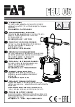
Operate the FOREMAN by pulling the Handle 

toward the work surface.

Lubricate the Guide Rods and mechanical linkage 

for smooth operation.

Guide Rods

Semi-Automatic Electric Foreman DB110 Operation

Entirely electric, no compressed air needed. 

Motor rated at 3/4-HP and 8-amps

GENERAL OPERATION


(Fig. 5A)

To operate the Electric FOREMAN, fi rst place a workpiece under 
the clamping pad. Make sure that the clamping pad extends no 
more than 1/8” above the workpiece in the unclamped state. 
If more than a 1/8” gap exists, adjust the Clamping Pad to the 
correct height. See the “ADJUSTMENTS” section – “Adjusting the 
Clamping Pad” for more information. Secondly making sure all body 
parts and clothing are safely away from the Clamping Pad, Drill 
Guide and Drill Bit, pull the handle towards the work surface. This 
action will start the Drill Motor and the mechanical action of moving 
the Handle will be transferred to the clamping mechanism to hold 
the workpiece in position prior to drilling. Continue to pull the Handle 
slowly toward the table surface to complete the drilling cycle. Finish 
the drilling process by carefully guiding the Handle back to the 
starting position. This will stop the 
Drill Motor and release the Clamping Pad.
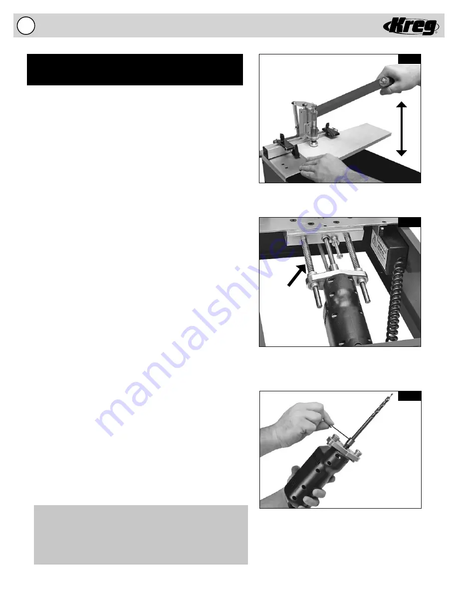
MAINTENANCE


(Fig. 5B & 5C)


1.

 Keep motor clean. Like any electric tool the Electric FOREMAN 

      needs to be kept free of excessive wood chips and dust.  
    Routinely remove waste material from inside the cabinet or  
    mount the machine above an open stand that will not allow the  
    waste material to accumulate.
 

2.

 Lubricate Guide Rods. Periodically service the Guide Rods with

      a dry fi lm lubricant like Dri-Tool™ Lubricant from Empire 
      Manufacturing. A dry fi lm lubricant will not collect wood chips 
      and dust and will extend the life of the Bearings and the Guide 
      Rods. See the “ADJUSTMENTS” section – “Changing the
    Drill Bit” for more information on how to perform this  


    maintenance. The mechanical linkage associated with the  
    clamping mechanism should be lubricated periodically to
    ensure free movement of its parts.
 

3.

 Use a sharp Drill Bit. You can expect to drill between 4,000 and 

    5,000 holes in Oak with your #DKDB drill bit before the bit will  
    need to be sharpened. This baseline was established using the  
    factory settings described in the owner’s manual. Adjust your  
    sharpening schedule for your settings and the material that you  
    may be drilling. Keeping the Drill Bit clean and free of pitch, 
    resin, and glue will signifi cantly add to the life of the Drill Bit
    and increase the number of holes between sharpening. You
    can easily clean the Drill Bit with a proprietary cleaner like
    Blade Saver™ from Empire Manufacturing.


WARNING! Even a dirty Drill Bit can be very sharp, exercise

    extreme caution when handling the cutting edges of the Drill Bit. 
    After cleaning you can coat the Drill Bit with a proprietary lubricant 
    designed for cutting wood such as OptiCut-XL™ from Empire 
    Manufacturing. To change the Drill Bit see the “ADJUSTMENTS” 
    section – “Changing the Drill Bit” for more information.

DB110 Electric - General Operation/Maintenance

Summary of Contents for DB110

Page 1: ...R R FOREMAN INSTRUCTIONAL MANUAL DB55 Pneumatic DB110 Electric Models Electric Foreman Item DB110 Item DB55 Pneumatic Foreman Patents pending 6 2010 DB5305 Rev C ...

Page 2: ...ttention As with all machinery there are certain hazards involved with operation and use of the machine Using the machine with respect and caution will considerably lessen the possibility of personal injury However if normal safety precautions are overlooked or ignored personal injury to the operator may result This machine was designed for specific applications only Kreg strongly recommends that ...

Page 3: ... important not to restrict air flow anywhere else coming to the machine To make sure you are getting the maximum amount of air to the machine we don t recommend using a hose extension 1 Disconnect the machine from the air supply 2 Remove the Black Acrylic Top to gain access to the inside of the machine 3 Disconnect the air supply line from the Air Motor by pushing in the collar on the inlet fittin...

Page 4: ...ckbacks occur when the workpiece binds up while being drilled causing it to twist jump and possibly become airborne To avoid kickbacks and potential injury always use sharp drill bits keep the machine aligned and maintained properly and adequately secure support the workpiece Turn machine off before adjusting Never adjust the fence swing stop clamping cylinder depth stop drill bit or any other par...

Page 5: ...it will operate properly and perform as intended Check for alignment of moving parts binding of moving parts breakage of parts mounting and any other conditions that may affect its operation A guard or other part that is damaged should be properly repaired or replaced as soon as possible preceding any additional use Do not use the machine if you are not qualified to make these sorts of assessments...

Page 6: ...orets bien aiguisés entretenez bien la machine et maintenez son alignement et fixez ou supportez bien la pièce Éteignez la machine avant d effectuer des ajustements N ajustez jamais le guide le dispositif anti oscillation le cylin dre de serrage la butée de profondeur de mortaise le foret ou tout autre élément de la machine pendant qu elle est en marche Attendez l arrêt complet de la machine Assur...

Page 7: ... garantir que la machine fonctionnera convenablement Vérifiez l alignement des pièces mobiles le montage et s il y a des pièces mobiles grippées ou des pièces brisées ainsi que toutes les autres conditions pouvant influencer son fonctionnement Un dispositif de sécurité ou toute autre pièce endommagée doit être réparée ou remplacée convenablement dès que possible avant tout autre usage N utilisez p...

Page 8: ...Tower Fig 3B 4B To attach the Mechanical Clamping Tower a bolt must be secured that is located on the underside of the machine This operation may be performed with the machine placed on its side on a workbench to more easily reach the bolt Refer to figure 3B and 4B for assembly Location of the bolt is the same for electric and pneumatic models 1 Remove all packing material from the Mechanical Clam...

Page 9: ...on its side on a workbench to more easily reach the bolt Refer to figure 3B and 4B for assembly Location of the bolt is the same for electric and pneumatic models 1 Remove all packing material from the Pneumatic Clamping Tower prior to attaching the Tower to the Fence The Air Cylinder is connected to the machine via the small diameter air supply line be careful not to twist or disconnect the air s...

Page 10: ...inely remove waste material from inside the cabinet or mount the machine above an open stand that will not allow the waste material to accumulate 2 Lubricate Guide Rods Periodically service the Guide Rods with a dry film lubricant like Dri Tool Lubricant from Empire Manufacturing A dry film lubricant will not collect wood chips and dust and will extend the life of the Bearings and the Guide Rods S...

Page 11: ...nt thicknesses When adjusting the Fence make sure that the Fence remains perpendicular to the Guide Plate A Reference Scale has been provided to approximate the fence setting for 1 2 3 4 and 1 1 2 thick material These correspond to the A B and C lines on the Reference Scale Step 1 Loosen the 2 Socket head Cap Screws contained below the surface of the Fence as shown in fig 6A Step 2 Align the Fence...

Page 12: ...the Handle until the Drill Bit pilot point is slightly away from the Fence 5 Adjust the Depth Stop Adjusting Screw till the Head contacts the Motor Mount 6 Tighten the Lock Nut to lock the Depth Stop Adjusting Screw in position 7 Place the Black Acrylic Top back on the machine Adjusting the Clamping Pad Height Fig 7B The Clamping Pad can be adjusted for material of different thicknesses The factor...

Page 13: ...rical supply you can be certain the Drill Bit will not accidentally engage while you are performing this adjustment 1 Disconnect the machine from the electrical supply 2 Remove the Black Acrylic Top to gain access to the inside of the machine 3 Lift the Tool Plate as it pivots on the hinges till the Safety Latch engages to hold the Tool Plate in position 4 Remove the Clevis and Cotter Pin from the...

Page 14: ...ill Motor An Automatic Oil Lubricator is installed on the Pneumatic FOREMAN and set to perform correctly at the factory See the ADJUSTMENTS section Adjusting the Automatic Oil Lubricator for more information 2 Lubricate Guide Rods Periodically service the Guide Rods with a dry film lubricant like Dri Tool Lubricant from Empire Manufacturing A dry film lubricant will not collect wood chips and dust...

Page 15: ...ure that the Fence remains perpendicular to the Guide Plate A Reference Scale has been provided to approximate the fence setting for 1 2 3 4 and 1 1 2 thick material These correspond to the A B and C lines on the Reference Scale Step 1 Loosen the 2 Socket head Cap Screws contained below the surface of the Fence as shown in fig 10A Step 2 Align the Fence perpendicular to the Guide Plate for the set...

Page 16: ...ylic Top back on the machine Adjusting the Clamping Cylinder Height Fig 11B The Clamping Cylinder can be adjusted for material of different thicknesses The factory setting will clamp materials of approximate thicknesses between 1 2 and 3 4 For materials thicker than 7 8 the Clamping Cylinder will need to be moved upward to allow the material to locate below the Clamp Pad Before adjusting the Clamp...

Page 17: ...ved to the operating position unless the machine is DISCONNECTED from the AIR SUPPLY 1 Disconnect the machine from the air supply 2 Remove the Black Acrylic Top to gain access to the inside of the machine 3 Disconnect the air supply line from the Air Motor by pushing in the collar on the inlet fitting of the Air Motor and simultaneously pull out the tubing 4 Lift the Tool Plate as it pivots on the...

Page 18: ... the distributor from which the FOREMAN Pocket Hole Boring Machine was purchased or you may contact Kreg Tool Company directly Proof of purchase will be required before remedy will be provided under the terms of this warranty Kreg Tool Company assumes no responsibility for products which are returned without prior authorization Kreg Tool Company s obligations under this warranty shall be exclusive...

Page 19: ...R Notes 18 ...

Page 20: ...R Notes Kreg Tool Company 201 Campus Drive Huxley IA 50124 800 447 8638 www kregtool com R ...

Reviews: