background image

Kramer Protocol 3000 


31 

31 

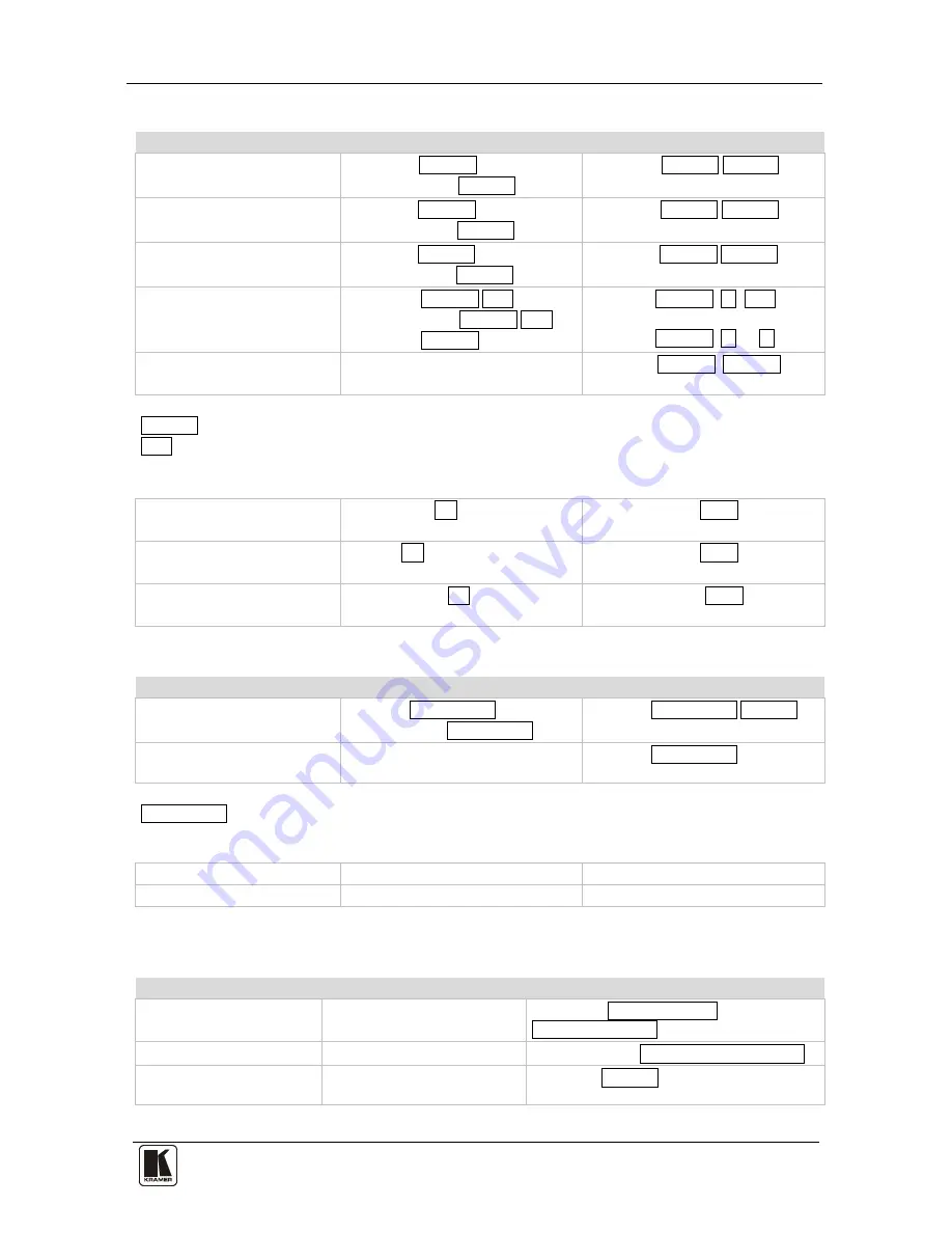
11.3.4 Preset Commands  

Command 

Syntax 

Response 

Store current connections to 

preset 

PRST-STO PRESET  

Short form: PSTO PRESET  

PRST-STO PRESET RESULT 
 

Recall saved preset 

PRST-RCL PRESET 

Short form: PRCL PRESET  

PRST-RCL PRESET RESULT 
 

Delete saved preset 

PRST-DEL PRESET  

Short form: PDEL PRESET  

PRST-DEL PRESET RESULT 
 

Read video connections from 

saved preset  

PRST-VID? PRESET,OUT 

Short form: PVID? PRESET,OUT 

PRST-VID? PRESET, * 

PRST-VID PRESET, IN>OUT 
 
PRST-VID PRESET, IN>1, IN>2,…  

Read saved presets list 

PRST-LST?  
Short form: PLST?  

PRST-LST PRESET, PRESET, …  
 

Parameter Description: 

PRESET = Preset number. 

OUT = Output in preset to display, '*' for all. 


Examples: 

Store current video connections 

to preset 5 

#PRST-STO 5CR 

~PRST-STR 5 OKCRLF 
 

Recall video connections from 

preset 3 

#PRCL 3CR 

~PRST-RCL 3 OKCRLF 
 

Show source of video output 2 

from preset 3 

#PRST-VID? 3,2CR 

~PRST-VID 3: 4>2 CRLF 
 

11.3.5 Operation Commands  

Command 

Syntax 

Response 

Lock front panel 

LOCK-FP LOCK-MODE  

Short form: LCK LOCK-MODE 

LOCK-FP LOCK-MODE RESULT 

Get front panel locking state 

LOCK-FP? 
 

LOCK-FP LOCK-MODE 

Parameter Description: 

LOCK-MODE = Front panel locking state:  

 ‘0’ or ‘off’ to unlock front panel buttons 
 ‘1’ or ‘on’ to lock front panel buttons 

Reset device 

RESET 

RESET OK 

Switch to protocol 2000* 

P2000 

P2000 OK 

* Protocol 2000 has a command to switch back to ASCII protocol (like Protocol 3000) 

11.3.6 Machine Information Commands  

Command 

Syntax 

Response 

Read in/out count 

INFO-IO?  

INFO-IO: IN INPUTS_COUNT, OUT 

OUTPUTS_COUNT  

Read max preset count 

INFO-PRST?  

INFO-PRST: VID PRESET_VIDEO_COUNT 

Reset to factory default 

configuration 

FACTORY 

FACTORY RESULT 

Summary of Contents for VS-88SDI

Page 1: ...Kramer Electronics Ltd Preliminary USER MANUAL Model VS 88SDI...

Page 2: ...ossover Cable 14 6 5 2 Connecting the ETHERNET Port via a Network Hub Straight Through Cable 15 6 6 Configuring the Ethernet Port 15 6 7 Controlling via the Ethernet Port 17 6 8 Using the Ethernet Res...

Page 3: ...000 Commands 30 11 3 1 Device Initiated Messages 30 11 3 2 Result and Error Codes 30 11 3 3 Basic Routing Commands 30 11 3 4 Preset Commands 31 11 3 5 Operation Commands 31 11 3 6 Machine Information...

Page 4: ...r 6 Table 3 Machine DIP Switch Settings 11 Table 4 DIP Switch Settings 12 Table 5 Genlock Settings 13 Table 6 VS 88SDI Technical Specifications 21 Table 7 Communication Parameters 22 Table 8 VS 88SDI...

Page 5: ...er cord2 This user manual and rack ears 3 2 Getting Started We recommend that you Unpack the equipment carefully and save the original box and packaging materials for possible future shipment Review t...

Page 6: ...KRAMER SIMPLE CREATIVE TECHNOLOGY Getting Started 2 2 1 Quick Start This quick start chart summarizes the basic setup and operation...

Page 7: ...to the bi level or tri level genlock input2 The VS 88SDI is housed in a 19 1U rack mountable enclosure and is fed from a 100 240 VAC universal switching power supply The unit can be controlled via the...

Page 8: ...influence signal quality and position your Kramer VS 88SDI away from moisture excessive sunlight and dust to avoid interference deterioration in signal quality due to poor matching and elevated noise...

Page 9: ...Your VS 88SDI 5 Figure 1 VS 88SDI...

Page 10: ...inate the genlock source 75 or release for looping 14 LOOP BNC Connector Connects to the genlock connector of the next unit in the line 15 INPUT BNC Connectors Connects to the serial digital video sou...

Page 11: ...s away from the machine This distance can be extended to up to 60 meters when used with three extension cables2 Before using the external IR receiver be sure to arrange for your Kramer dealer to inser...

Page 12: ...KRAMER SIMPLE CREATIVE TECHNOLOGY Installing the VS 88SDI in a Rack 8 5 Installing the VS 88SDI in a Rack This section provides instructions for rack mounting the 1U unit...

Page 13: ...4 Optionally2 A genlock source to the GENLOCK BNC connector connect The LOOP BNC connector to the GENLOCK connector of the next unit in the line and release the TERM button for looping3 5 Connect a P...

Page 14: ...o the VS 88SDI via an RS 232 connection using for example a PC Note that a null modem adapter connection is not required To connect to the VS 88SDI via RS 232 Connect the RS 232 9 pin D sub rear panel...

Page 15: ...IP SWITCH 1 2 3 4 1 Single or master unit1 OFF ON OFF OFF OFF OFF OFF OFF 2 OFF ON OFF OFF 3 ON ON OFF OFF 4 OFF OFF ON OFF 5 ON OFF ON OFF 6 OFF ON ON OFF 7 ON ON ON OFF 8 OFF OFF OFF ON 9 ON OFF OFF...

Page 16: ...ort You can operate the VS 88SDI via the RS 485 port from a distance of up to 1200 meters 3900ft using any device equipped with an RS 485 port for example a PC For successful communication you must se...

Page 17: ...ing Genlocked Video Signals The genlock feature lets you switch genlocked video signals according to timing of the GENLOCK reference input1 1 Connect the GENLOCK cable 2 To set the genlock timing pres...

Page 18: ...or identification of the factory default IP address 1 After connecting the Ethernet port configure your PC as follows of the VS 88SDI during the initial configuration 1 Right click the My Network Plac...

Page 19: ...ct the Ethernet port of the VS 88SDI to the Ethernet port on a network hub or network router via a straight through cable with RJ 45 connectors 6 6 Configuring the Ethernet Port To configure the Ether...

Page 20: ...he VS 88SDI Select Ethernet if you know the IP address number1 or the machine name The default name for the machine is KRAMER_XXXX2 Serial if you are connected via a serial port 3 Click OK The Device...

Page 21: ...olling a standalone unit via RS 232 or the Ethernet configure the unit as master Mach No 1 see section 6 1 1 6 8 Using the Ethernet Reset Button To reset Ethernet parameters to the factory defaults 1...

Page 22: ...ONFIRM modes When the VS 88SDI operates in the AT ONCE mode pressing an OUT IN combination implements the switch immediately In the CONFIRM mode the change does not take place until the TAKE button is...

Page 23: ...mode when the TAKE button is illuminated do the following 1 Press an OUT IN combination The 7 segment display flashes2 2 Press the TAKE button to confirm the action The 7 segment display stops flashi...

Page 24: ...key for three seconds The LOCK key illuminates and the front panel keys are inactivated To unlock the front panel press and hold the illuminated LOCK key until the light turns off The front panel keys...

Page 25: ...m the front panel The IR remote can only set 8 preset configurations equivalent to OUT1 to OUT8 8 Technical Specifications The VS 88SDI technical specifications are shown in Table 6 Table 6 VS 88SDI T...

Page 26: ...ress and hold Output 1 and Output 3 simultaneously Ethernet Default Settings Reset Settings IP Address 192 168 1 39 Power cycle the unit while holding in the Factory Reset button located on the rear p...

Page 27: ...cking the desktop icon P3K Wizard The P3K Wizard screen appears1 Figure 8 P3K Wizard Screen 3 Click the Connect button to open the Connect window 1 The screens appearing in this manual are examples of...

Page 28: ...TECHNOLOGY Using the P3K Wizard 24 Figure 9 Connect Window 4 Choose the appropriate type of connection Ethernet BY IP BY NAME or SERIAL USB and click OK The Connect window disappears and the Device Pr...

Page 29: ...e white fields as required and click SET 10 2 Updating the VS 88SDI Firmware The VS 88SDI uses a microcontroller that runs firmware located in FLASH memory The latest version of firmware and installat...

Page 30: ...the front panel buttons or by transmitting protocol commands To switch protocols using the front panel buttons To choose Protocol 2000 press LOCK and OUT 2 at the same time To choose the Protocol 300...

Page 31: ...er_1 Parameter_2 CR 11 2 1 2 Command String Formal syntax with commands concatenation and addressing Start Address Body Delimiter Destination_id Command_1 Parameter1_1 Parameter1_2 Command_2 Parameter...

Page 32: ...for K NET K NET Device ID followed by Query sign follows some commands to define a query request Message closing character CR For host messages carriage return ASCII 13 CRLF For machine messages carr...

Page 33: ...When chaining commands enter the message starting character and the message closing character only once at the beginning of the string and at the end Commands in the string do not execute until the cl...

Page 34: ...N 1 IN 2 Parameter Description IN Input number or 0 to disconnect output Connection character between in and out parameters OUT Output number or for all outputs Examples Switch video input 2 to output...

Page 35: ...STO 5CR PRST STR 5 OKCRLF Recall video connections from preset 3 PRCL 3CR PRST RCL 3 OKCRLF Show source of video output 2 from preset 3 PRST VID 3 2CR PRST VID 3 4 2 CRLF 11 3 5 Operation Commands Co...

Page 36: ...IP_ADDRESS RESULT Read IP address NET IP Short form NTIP NET IP IP_ADDRESS Read MAC address NET MAC Short form NTMC NET MAC MAC_ADDRESS Set subnet mask NET MASK SUBNET_MASK Short form NTMSK NET MASK S...

Page 37: ...81 IN 2 01 83 88 81 01 83 87 81 01 83 86 81 01 83 85 81 01 83 84 81 01 83 83 81 01 83 82 81 01 83 81 81 IN 3 01 84 88 81 01 84 87 81 01 84 86 81 01 84 85 81 01 84 84 81 01 84 83 81 01 84 82 81 01 84...

Page 38: ...BYTE Bit 7 Defined as 1 I6 I0 INPUT When switching i e instruction codes 1 and 2 the INPUT 7 bits is set as the input number which is to be switched Similarly if switching is done via the machine s fr...

Page 39: ...ber of setups 1 for video 3 for SDI 4 for remote panel 5 for RS 422 controller 14 NOTES on the above table NOTE 1 When the master switcher is reset e g when it is turned on the reset code is sent to t...

Page 40: ...d the version number would be HEX codes 7D 83 85 81 i e 128dec 3dec for 2nd byte 128dec 5dec for 3rd byte If the OUTPUT is set as 1 then the ASCII coding of the lettering following the machine s name...

Page 41: ...theractsofnature ii Product modification orfailureto followinstructions supplied with theproduct iii Repairorattemptedrepairby anyonenot authorized byKramer iv Anyshipment oftheproduct claims must bep...

Page 42: ...or the latest information on our products and a list of Kramer distributors visit our Web site www kramerelectronics com where updates to this user manual may be found We welcome your questions commen...

Reviews: