P/N: 2900-301419 Rev 1
www.kramerAV.com
USER MANUAL
MODEL:
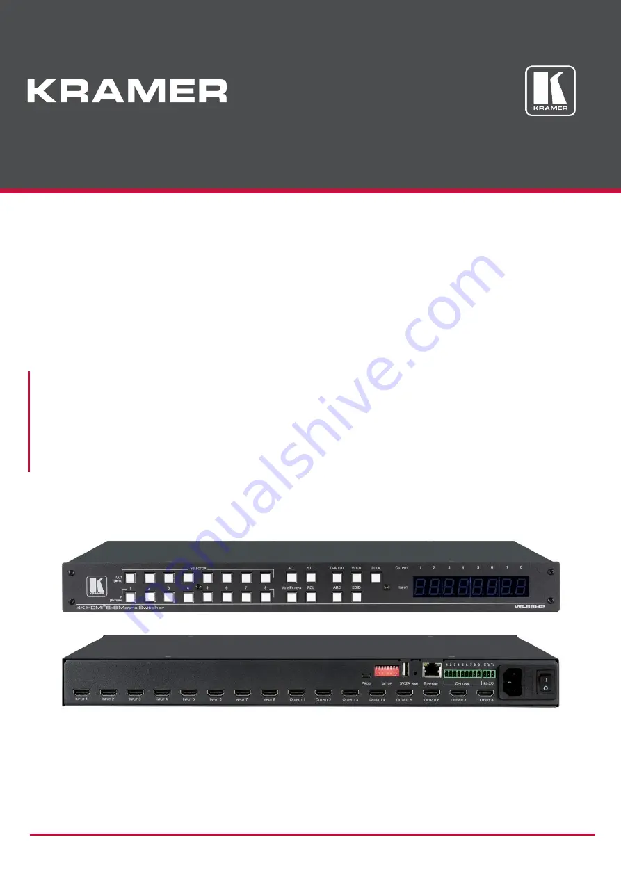
VS-88H2, VS-66H2, VS-84H2, VS-48H2 Matrix Switcher
Page 1: ...P N 2900 301419 Rev 1 www kramerAV com USER MANUAL MODEL VS 88H2 VS 66H2 VS 84H2 VS 48H2 Matrix Switcher ...
Page 2: ...tching Mode 23 Setting Switching Speed 23 Setting HDCP 24 Copying the EDID 25 Firmware Upgrade 26 Using Embedded Web Pages 27 Switching and Setting Ports 29 Changing Device Settings and Upgrading Firmware 40 Managing Web Page Security 42 Managing Timeout Settings 46 Setting Switching Modes 48 Setting Step in Devices 51 Managing the EDID 53 Viewing About Page 57 Technical Specifications 58 Default ...
Page 3: ...tion in signal quality due to poor matching and elevated noise levels often associated with low quality cables Do not secure the cables in tight bundles or roll the slack into tight coils Avoid interference from neighboring electrical appliances that may adversely influence signal quality Position your Kramer VS 88H2 away from moisture excessive sunlight and dust Caution This equipment is to be us...
Page 4: ...specific feature is described The Matrix Switcher is a high quality switcher for 4K 60Hz 4 4 4 HDMI signals and embedded audio It reclocks and equalizes the signals and can route any one of the selectable HDMI HDCP compliant sources to any or all outputs simultaneously The Matrix Switcher offers a flexible audio scheme where any HDMI digital audio input can be routed to any HDMI digital audio outp...
Page 5: ...al controller Ethernet port via LAN 7 segment display indicating the video and audio status and other functions Audio breakaway and AFV audio follow video operation support Efficient power saving features Includes non volatile memory that retains the last settings after switching the power off and then on again Flexible Connectivity HDMI signal switching Independent Audio Routing Any embedded digi...
Page 6: ...Controlling your VS 88H2 Control your Matrix Switcher directly via the front panel push buttons or By RS 232 serial commands transmitted by a touch screen system PC or other serial controller Via the Ethernet using built in user friendly web pages ...
Page 7: ...1 VS 88H2 8x8 H2 Matrix Switcher Front Panel Figure 2 VS 66H2 6x6 Matrix Switcher Front Panel Figure 3 VS 84H2 8x4 Matrix Switcher Front Panel Figure 4 VS 48H2 4x8 Matrix Switcher Front Panel The behavior of the front panel buttons and the 7 segment display changes along with the operation modes For further details see Operating VS 88H2 via Front Panel Buttons on page 13 ...
Page 8: ...xample setting Mute mode Pattern mode and so on For switching press ALL and then a specific IN button to route the selected input to all outputs For example press ALL and then IN 2 to route input 2 to all the outputs STO Buttons Press STO to store the current switching setting to a preset button RCL Buttons Press RCL to recall the switching setting from a preset button ARC Button Press to set ARC ...
Page 9: ...o HDMI acceptors PROG Mini USB Port Use for firmware upgrade or communication connecting to a PC or a serial controller SETUP DIP Switches N A 5V 2A USB Port Use to charge a device Reset Button Press and hold while powering the device to reset IP settings to factory default values ETHERNET RJ 45 Port Connect to your LAN OPTIONAL Terminal Block Connectors N A RS 232 3 pin Terminal Block Connectors ...
Page 10: ...ion Caution Mount VS 88H2 before connecting any cables or power Warning Ensure that the environment e g maximum ambient temperature air flow is compatible for the device Avoid uneven mechanical loading Appropriate consideration of equipment nameplate ratings should be used for avoiding overloading of the circuits Reliable earthing of rack mounted equipment should be maintained Mount VS 88H2 in a r...
Page 11: ... illustrated in the example in Figure 9 do the following 1 Connect up to eight video sources to the INPUT HDMI Connector from INPUT1 to INPUT 8 For example connect Laptops to INPUT 1 3 4 and 8 HDMI connectors Blu ray players to the INPUT 2 and INPUT 6 HDMI connectors 2 Connect the eight video OUTPUT HDMI Connectors from OUTPUT 1 to OUTPUT 8 to up to eight acceptors For example connect OUTPUT 1 6 a...
Page 12: ...Directly to a PC on page 10 Via a network hub switch or router using a straight through cable see Connecting the Ethernet Port via a Network Hub or Switch on page 12 If you want to connect via a router and your IT system is based on IPv6 speak to your IT department for specific installation instructions Connecting the Ethernet Port Directly to a PC You can connect the Ethernet port of the VS 88H2 ...
Page 13: ...either Internet Protocol Version 6 TCP IPv6 or Internet Protocol Version 4 TCP IPv4 depending on the requirements of your IT system 5 Click Properties The Internet Protocol Properties window relevant to your IT system appears as shown in Figure 11 or Figure 12 Figure 11 Internet Protocol Version 4 Properties Window ...
Page 14: ...ment Figure 13 Internet Protocol Properties Window 7 Click OK 8 Click Close Connecting the Ethernet Port via a Network Hub or Switch You can connect the Ethernet port of the VS 88H2 to the Ethernet port on a network hub or using a straight through cable with RJ 45 connectors Control Configuration via the Ethernet Port To control several units via Ethernet connect the Master unit Device 1 via the E...
Page 15: ...ons and 7 segment display enter normal operation The 7 segment display shows the video IN OUT status The current operation mode button illuminates VIDEO by default An illuminated IN PATTERN SELECTOR Button indicates an active signal connected to the input An illuminated OUT MUTE SELECTOR Button indicates that an acceptor is connected to the output The VS 88H2 front panel buttons enable performing ...
Page 16: ...ignal Simultaneously You can select the digital audio signal to switch to the output together with the video signal To switch the audio and video signals together to an output 1 Press D AUDIO and VIDEO simultaneously The button illuminates and the 7 segment LED Display shows the current IN OUT video status 2 Press an OUT MUTE SELECTOR Button 1 to 8 The 7 segment display LED under the selected outp...
Page 17: ...rypted input is routed through the matrix to a non HDCP screen the video is not be presented and the non HDCP screen turns black On the 7 segment display A digit from 1 to 8 shows the input number that is currently routed to the output P under an output number indicates that a pattern is routed to that output 0 under an output number indicates that the output is muted 2 Press an OUT MUTE SELECTOR ...
Page 18: ...nal from a DVD player is detected on that input An illuminated output button means that a display that supports LPCM audio is connected to that output A dark button means either that the display that is connected does not support audio or that a display is not connected at all A flashing output button means that a display is connected that supports LPCM Dolby digital AC 3 and NLPCM audio On the 7 ...
Page 19: ... device via the embedded web pages see Switching Audio in Breakaway Mode on page 38 for further reference You can then route the audio output to the input either via the embedded web pages see Switching ARC to an Input on page 39 or via the front panel buttons The following examples show how the output 6 ARC audio signal is routed to input 3 as illustrated in Figure 14 Figure 14 ARC Audio Routing ...
Page 20: ...t Audio Signal You can mute unmute an audio signal and a video signal separately To mute unmute an audio signal 1 Press D AUDIO The D AUDIO button illuminates 2 Press an OUT MUTE button 1 to 8 Press ALL instead of an output button to mute unmute all the outputs All the 7 segment display LEDs flash 3 Press MUTE PATTERN The audio signal is muted unmuted on the output A muted output appears as 0 on t...
Page 21: ... MUTE PATTERN On the front panel buttons An illuminated output button means that a display is connected on that output An illuminated input button indicates the current pattern selected On the 7 segment display P under an output number indicates that a pattern is routed to that output under an output number indicates that a video input is routed to that output 0 under an output number indicates th...
Page 22: ... an output number indicates that a pattern is routed to that output under an output number indicates that a video input is routed to that output 0 under an output number indicates that the output is muted 2 Press an OUT MUTE button 1 to 8 The 7 segment display LED under the selected output flashes Press ALL instead of an output button to route a pattern to all the outputs All the 7 segment display...
Page 23: ...is routed to that output under an output number indicates that a video input is routed to that output 0 under an output number indicates that the output is muted 2 Press an OUT MUTE button 1 to 6 The 7 segment display LED under the selected output flashes Press ALL instead of an output button to route a pattern to all the outputs All the 7 segment display LEDs flash 3 Press an input button to sele...
Page 24: ...l mode OUT 1 corresponds to setup 1 IN 1 corresponds to setup 9 and so on Figure 16 VS 88H2 8x8 H2 Matrix Switcher Front Panel To store a setup 1 Press STO The STO button illuminates 2 Press an IN or an OUT button from 1 to 8 The selected button flashes 3 Press STO The current device state is stored to the selected setup and the STO button no longer illuminates To recall a setup 1 Press RCL The RC...
Page 25: ...an output button or press ALL The corresponding 7 segment display LEDs flash and LOCK button flashes 3 Press IN 1 IN 2 or IN 3 4 Press LOCK The switching mode is set for the selected output Setting Switching Speed Set the following switching speed modes separately for each output Extra Fast switch speed IN 1 Fast switch speed IN 2 Normal switch speed IN 3 To select the switching speed 1 Press STO ...
Page 26: ...t HDCP on or off 1 Press and hold EDID and RCL Both buttons illuminate and the IN buttons indicate the HDCP status HDCP 1 4 enabled on IN button is illuminated HDCP 2 2 enabled on IN button flashes HDCP disabled off IN button is off 2 Press one or more input buttons to change their status The LOCK button flashes 3 Press LOCK The HDCP settings are saved ...
Page 27: ...file via web page A digit under an output number indicates the output from which the EDID was copied 2 Press one or more input buttons or ALL The 7 segment display LEDs of the selected inputs flash 3 Press the output button with a connected display corresponding to the output from which you want to copy the EDID 4 Press EDID Wait for about 5 seconds for the device to copy the EDID from the connect...
Page 28: ...a The Ethernet using embedded web pages see Performing Firmware Upgrade on page 41 By USB or RS 232 using Kramer K UPLOAD tool The latest firmware version and the latest version of K UPLOAD and installation instructions can be downloaded from the Kramer Web site at www kramerav com downloads VS 88H2 ...
Page 29: ...ersion Browser Windows 7 Firefox Chrome Safari 10 Edge Firefox Chrome Mac 10 11 Safari iOS 10 3 2 Safari The VS 88H2 web pages enable performing the following Switching and Setting Ports on page 29 Changing Device Settings and Upgrading Firmware on page 40 Managing Web Page Security on page 42 Managing Timeout on page 46 Setting Switching Modes on page 48 Setting Step in Devices on page 51 Managin...
Page 30: ...re 17 Using the Embedded Web Pages the Authentication Window 3 Enter the Username and Password and click OK The Switching page appears Figure 18 Switching Page with Navigation List on Left 4 Click the desired web page or click the arrow to hide the navigation list ...
Page 31: ...ge 37 Switching Audio in Breakaway Mode on page 38 Switching ARC to an Input on page 39 Switching an Input to an Output This section contains information on switching using webpages For information on switching using front panel buttons see Routing Signals on page 14 To switch an input to an output 1 In the Navigation pane click Switching The Switching page appears Figure 18 2 Select the AFV tab T...
Page 32: ...ching The Switching page appears Figure 18 2 Select the AFV tab The Audio follow video tab is displayed Figure 18 3 Click on an output or input button Figure 19 Switching Page Output Button The settings window appears Figure 20 Switching Page Editing the Output Button Settings 4 Type a new label name up to 16 alpha numeric characters and click The button label is changed ...
Page 33: ...ct the AFV tab The Audio follow video tab is displayed Figure 18 3 Click on an output button Figure 19 The output settings window appears Figure 20 4 Select HDCP dropdown box and set HDCP support to Follow input HDCP Support HDCP 1 4 or Support HDCP 2 2 Output HDCP icon appears 2nd icon on button when output is without HDCP Output HDCP icon appears 2nd icon on button when output is HDCP 1 4 Output...
Page 34: ...gation pane click Switching The Switching page appears Figure 18 2 Select the AFV tab The Audio follow video tab is displayed Figure 18 3 Click on an output button Figure 19 The input settings window appears Figure 21 Switching Page Editing the Input Button Settings 4 Select HDCP dropdown box and set HDCP to No HDCP HDCP 1 4 or HDCP 2 2 Input HDCP icon appears on input button when output is withou...
Page 35: ...ting Unmuting Video This section contains information on muting unmuting video using webpages For information on muting unmuting video using front panel buttons see Muting Unmuting an Output Video Signal on page 18 indicates video is not muted indicates video is muted To mute video 1 In the Navigation pane click Switching The Switching page appears Figure 18 2 Select the AFV tab The Audio follow v...
Page 36: ...s to and the output changes to audio breakaway mode To set audio follow video AFV mode 1 In the Navigation pane click Switching The Switching page appears Figure 18 2 Select the AFV tab The Audio follow video tab is displayed Figure 18 3 Click the AFV Breakaway icon The AFV Breakaway icon changes to and the output changes to audio follow video mode gray colored indicates that the device is in the ...
Page 37: ...ching The Switching page appears Figure 18 2 Select Audio break away tab The Audio follow video tab is displayed Figure 18 3 Check the ARC check boxes under the Audio Outputs column to enable the device to accept audio signals from the selected outputs When in the ARC mode the output buttons of the selected outputs illuminate For example Output 1 6 7 and 8 are checked therefore they are ARC enable...
Page 38: ...age appears Figure 18 2 Select the AFV tab The Audio follow video tab is displayed Figure 18 3 Click on an input button Figure 19 The input settings window appears Figure 21 4 Slide ARC Step in to ARC mode 5 Click the settings button The input ARC Settings window appears by default the output source is set to output 1 Figure 23 Input 3 ARC Settings 6 Select the desired HDMI output for example 6 Fi...
Page 39: ...o an output 1 In the Navigation pane click Switching The Switching page appears Figure 18 2 Select the AFV tab The Audio follow video tab is displayed Figure 18 3 Select the Patterns tab The pattern buttons appear Figure 25 Switching page with pattern buttons on Right 4 Click one or more output buttons or check the Outputs box to select all the outputs The selected buttons change color to purple 5...
Page 40: ...ependently If HDMI input port and HDMI output port ARC mode are enabled you can switch a selected HDMI output port ARC to any HDMI input port ARC To switch an audio input to an audio output in Breakaway mode 1 In the Navigation pane click Switching The Switching page appears Figure 18 2 Select the Audio break away tab The Audio break away tab is displayed Figure 26 Switching page Breakaway Mode 3 ...
Page 41: ...he Audio break away tab The Audio break away tab is displayed Figure 26 3 Check the ARC check boxes to ARC enable selected outputs under the Audio Outputs column EXAMPLE Output 2 and 4 are checked ARC enabled so they can be switched as ARC signals Figure 28 Switching Page Output 2 and 4 ARC Enabled Make sure that the acceptor on the output side has ARC capabilities see Enabling ARC Input on page 3...
Page 42: ... Upgrade on page 41 Changing Ethernet Settings To change the Ethernet settings 1 In the Navigation pane click Device Settings The Device Settings page appears Figure 29 Device Settings Page 2 Uncheck check the DHCP check box 3 If DHCP is unchecked change any of the parameters IP Address Netmask and or Gateway 4 Click Save Changes After changing the IP number reload the web page with the new IP add...
Page 43: ... Button Figure 5 while powering the device to reset IP settings to factory default values Performing Firmware Upgrade This section contains information on upgrading the firmware using webpages For information on upgrading the firmware using By USB or RS 232 using Kramer K UPLOAD tool go to Kramer Web site at www kramerav com downloads VS 88H2 To perform firmware upgrade 1 In the Navigation pane cl...
Page 44: ... corner The Authentication web page enables performing the following functions Setting up a Password on page 42 Changing a Password on page 44 Setting up Free Access No Password on page 45 Setting up a Password To set up a password 1 In the Navigation pane click Authentication The Authentication page appears Figure 31 Authentication Page 2 Slide Activate Security to ON The Set Password dialog appe...
Page 45: ...alog appears Figure 33 Password Settings Page Security Activation Message 4 Click OK The connection is interrupted and authentication is required to access web pages Figure 34 Password Settings Page Security Log In 5 Type a Username Admin by default and Password and click Sign In The web page reloads and the lock icon in the upper right of the screen changes to ...
Page 46: ...ngs Page Password Protected 2 Type the existing password in the Old password text box and type the new password twice in both Admin password text boxes 3 Click The following message appears Figure 36 Password Settings Page Password Warning 4 Click OK The page is reloaded and can be accessed by entering the new password The web page reloads and the lock icon in the upper right of the screen changes...
Page 47: ...ane click Authentication The Authentication page appears Figure 37 Password Settings Page Password Protected 2 Set Activate Security to OFF Enter Password dialog appears 3 Enter the password and click confirm The following dialog appears Figure 38 Password Settings Page Deactivating the Security 4 Click OK The web page reloads and the lock icon in the upper right of the screen changes to ...
Page 48: ... enables performing the following functions Setting Timeout on page 46 Setting Support Audio Only on page 47 Setting Video Signal Lost Timer on page 47 Setting Timeout To set the timeout 1 In the Navigation pane click Timeout Settings The Timeout Settings page appears Figure 39 Timeout Settings Page 2 Set the specific output delay time If you do not want a specific output to shut down when an inpu...
Page 49: ...nal routed to the output remains active when the video source coming from a different input is deactivated Set Support audio only to OFF The audio signal routed to the output is deactivated together with the deactivation of the video source coming from a different input Setting Video Signal Lost Timer To set the video signal lost timer when in auto switching mode 1 In the Navigation pane click Tim...
Page 50: ... Mode to Manual on page 48 Setting Switching Mode to Priority on page 49 Setting Switching Mode to Last Connected on page 50 This feature can also be performed manually on VS 88H2 see Setting Switching Mode on page 23 Setting Switching Mode to Manual To set the switching mode to Manual 1 In the Navigation pane click Auto Switch Settings The Auto Switch Settings page appears Figure 40 Auto Switch S...
Page 51: ...to Switch Settings The Auto Switch Settings page appears Figure 40 2 Select an output and set the switching mode to Priority The following page appears Figure 41 Auto Switch Settings Page Setting the switching Priority 3 Drag and drop the inputs from the highest to the lowest priority The inputs are then switched according to the set priority to the selected output ...
Page 52: ...n the Navigation pane click Auto Switch Settings The Auto Switch Settings page appears Figure 40 2 Select an output and set the switching mode to Last Connected The following page appears Figure 42 Auto Switch Settings Page Last Connected Mode 3 Select the inputs that are included in the last connected scan that are switched to the selected output ...
Page 53: ...wing page appears Figure 43 Step In Settings Page Step in Device is not Connected To manage a step in device 1 Connect the HDMI output of a step in device for example DIP 30 to an HDMI input on the VS 88H2 2 In the Navigation pane click Step in Settings The Step in Settings page appears and the input button s to which the step in device s is connected turn s white Figure 44 Step In Settings Page D...
Page 54: ... a DIP 30 input HDMI IN 1 HDMI IN 2 or VGA The respective button on DIP 30 illuminates You can also press an input button on the DIP 30 The selected input is displayed on the web page 5 Check the outputs to which the inputs are routed 6 Press the STEP IN button on DIP 30 The selected step in button is routed to all the checked outputs Any time the output Step in configuration changes press the STE...
Page 55: ...on page 55 Copying an EDID from an Input to Another Input on page 55 Copying an EDID from an Output to an Input To copy an EDID from an output to an input 1 In the Navigation pane click EDID Management The EDID Management page appears Figure 46 EDID Management Page Select an EDID Source 2 Select a connected output as the EDID source The selected output button changes color to purple Make sure that...
Page 56: ...e selected input button s changes color to purple Figure 47 EDID Management Page Select an EDID output and input s 4 Click COPY The following EDID message appears Figure 48 EDID Page EDID Copy Message 5 Click OK The following message appears Figure 49 EDID Management Page Loading the EDID from Output to Input 6 Click OK The output EDID is copied ...
Page 57: ...nges color to purple 4 Click COPY and follow the instructions The default EDID is copied Copying an EDID from an Input to Another Input To copy the EDID from an input to another input s 1 In the Navigation pane click EDID Management The EDID Management page appears Figure 46 2 Scroll down and select an input from the list on the left The input button changes color to purple 3 Select one or more in...
Page 58: ... instructions The PC EDID is copied When viewing the 7 segment display in the EDID mode the input with EDID read from a file displayed as L Setting Input Port EDID Data Only for 24 Bits To set input port EDID data only for 24 bits 1 In the Navigation pane click EDID Management The EDID Management page appears Figure 46 2 Check Deep color OFF Input port setting EDID data is set only for 24 bits Set...
Page 59: ...bedded Web Pages 57 Viewing About Page The VS 88H2 About page lets you view the web page version and Kramer Electronics Ltd details To viewing the About page 1 In the Navigation pane click About Us The About page appears Figure 50 About Page ...
Page 60: ...pecified in HDMI 2 0 Control Front Panel Front panel buttons 7 segment display Power Consumption 600mA Source 100 240V AC 50 60Hz Regulatory Compliance Safety CE FCC Environmental RoHs WEEE Environmental Conditions Operating Temperature 0 to 40 C 32 to 104 F Storage Temperature 40 to 70 C 40 to 158 F Humidity 10 to 90 RH non condensing Enclosure Size 19 9 3 1U rack mountable Cooling Fan ventilatio...
Page 61: ...bnet Mask 255 255 0 0 Default Gateway 192 168 0 1 Default TCP Port 5000 Default UDP Port 50000 Number of TCP ports 8 Number of web clients 5 Default username Admin Default password Admin Full Factory Reset Front Panel Buttons Power off the device press and hold the LOCK EDID and STO buttons simultaneously for about 3 seconds while powering the device and then release Until all front panel buttons ...
Page 62: ...0 x 400p at 88Hz IBM XGA2 640 x 480p at 60Hz IBM VGA 640 x 480p at 67Hz Apple Mac II 640 x 480p at 72Hz VESA 640 x 480p at 75Hz VESA 800 x 600p at 56Hz VESA 800 x 600p at 60Hz VESA 800 x 600p at 72Hz VESA 800 x 600p at 75Hz VESA 832 x 624p at 75Hz Apple Mac II 1024 x 768i at 87Hz IBM 1024 x 768p at 60Hz VESA 1024 x 768p at 70Hz VESA 1024 x 768p at 75Hz VESA 1280 x 1024p at 75Hz VESA 1152 x 870p at...
Page 63: ...o Front left right center No Rear left right center No Rear LFE No Report information Date generated 15 05 2019 Software revision 2 90 0 1020 Data source Real time 0x0041 Operating system 10 0 17134 2 Raw data 00 FF FF FF FF FF FF 00 2D B2 ED 03 01 00 00 00 14 1A 01 03 80 34 20 78 E2 B3 25 AC 51 30 B4 26 10 50 54 FF FF 80 81 8F 81 99 A9 40 61 59 45 59 31 59 71 4A 81 40 02 3A 80 18 71 38 2D 40 58 2...
Page 64: ...reset status EDID data All input ports use the default EDID data V mute Open the video Mute Open the audio Switch mode Manual Switch speed Extra fast switch ARC or de embedded De embedded Video Priority settings Lower input index has higher priority Auto Switching mode Priority Priority order is Highest for 1 and lowest for 8 Auto Switching settings All video inputs are routed to each of the video...
Page 65: ...P70 4096 2160P23 720P60 1400 1050P60rb 640 480P75 3840 2160P60 720P59 1366 768P60 640 480P72 3840 2160P30 720P50 1366 768P60rb 640 480P59 3840 2160P29 576P50 1360 768P60 680 480P60 3840 2160P25 576i50 1280 1024P60 1440 480I60 3840 2160P24 480P60 1280 960P60 1440 240P60 3840 2160P23 480P59 1280 768P60 1440 480P60 1080P60 480i60 1280 768P60rb 720 576P50 1080P59 480i59 1152 864P75 1440 576I50 1080P50...
Page 66: ...r s Suffix nn Command Parameter CR LF Command parameters Multiple parameters must be separated by a comma In addition multiple parameters can be grouped as a single parameter using brackets and Command chain separator character Multiple commands can be chained in the same string Each command is delimited by a pipe character Parameters attributes Parameters may contain multiple attributes Attribute...
Page 67: ... the audio follow video switching mode 1 brk sets the unit to the audio breakaway switching mode Get audio follow video mode status AFV CR AUD LEGACY COMMAND Set audio switch state When AFV switching mode is active this command cannot switch video COMMAND AUD in out_id in out_id CR FEEDBACK nn AUD in out_id CR LF nn AUD in out_id CR LF in Input number 0 disconnect output 1 HDMI IN 1 2 HDMI IN 2 3 ...
Page 68: ...3 4 HDMI OUT 4 5 HDMI OUT 5 6 HDMI OUT 6 7 HDMI OUT 7 8 HDMI OUT 8 connection_mode Connection mode 0 manual 1 priority switch 2 last connected switch Get the input auto switch mode for HDMI OUT 1 AV SW MODE 1 1 CR AV SW TIMEOUT Set auto switching timeout COMMAND AV SW TIMEOUT switching_mode time_out CR FEEDBACK nn AV SW TIMEOUT switching_mode time_out CR LF switching_mode Switching mode 0 Video si...
Page 69: ...K nn CPEDID edid_io src_id dst_type dest_bitmap CR LF edid_io EDID source type usually output 0 Input 1 Output 2 Default EDID src_id Number of chosen source stage For input source 1 HDMI IN 1 2 HDMI IN 2 3 HDMI IN 3 4 HDMI IN 4 5 HDMI IN 5 6 HDMI IN 6 7 HDMI IN 7 8 HDMI IN 8 For output source 0 Default EDID source 1 HDMI OUT 1 2 HDMI OUT 2 3 HDMI OUT 3 4 HDMI OUT 4 5 HDMI OUT 5 6 HDMI OUT 6 7 HDMI...
Page 70: ...R fpga_id expected_ver ver CR LF fpga_id FPGA id 1 expected_ver Expected FPGA version for current firmware ver Actual FPGA version Get current FPGA version FPGA VER 1 CR GEDID Get EDID support on certain input output For old devices that do not support this command nn ERR 002 CR LF is received COMMAND GEDID io_mode in_index CR FEEDBACK nn GEDID io_mode in_index size CR LF io_mode Input Output 0 In...
Page 71: ...s to allow identification of a specific device from similar devices COMMAND IDV CR FEEDBACK nn IDV ok CR LF IDV CR INFO IO LEGACY COMMAND Get in out count COMMAND INFO IO CR FEEDBACK nn INFO IO IN in_count OUT out_count CR LF in_count Number of inputs in the unit out_count Number of outputs in the unit Get inputs count INFO IO CR INFO PRST LEGACY COMMAND Get maximum preset count In most units vide...
Page 72: ...to save on device size Size of file data that is sent Using the Packet Protocol Send a command LDRV LOAD IROUT LDEDID Receive Ready or ERR If Ready a Send a packet b Receive OK on the last packet c Receive OK for the command Packet structure Packet ID 1 2 3 2 bytes in length Length data length 2 for CRC 2 bytes in length Data data length 2 bytes CRC 2 bytes 01 02 03 04 05 Packet ID Length Data CRC...
Page 73: ...ring Set the protocol permission level to Admin when the password defined in the PASS command is 33333 LOGIN Admin 33333 C R LOGIN Get current protocol permission level The permission system works only if security is enabled with the SECUR command For devices that support security LOGIN allows the user to run commands with an End User or Administrator permission level In each device some connectio...
Page 74: ...end Set the DNS name of the device to room 442 NAME room 442 CR NAME Get machine DNS name The machine name is not the same as the model name The machine name is used to identify a specific machine or a network in use with DNS feature on COMMAND NAME CR FEEDBACK nn NAME machine_name CR LF machine_name String of up to 14 alpha numeric chars can include hyphen not at the beginning or end Get the DNS ...
Page 75: ... IP address to 192 168 1 39 NET IP 192 168 001 039 C R NET IP Get IP address COMMAND NET IP CR FEEDBACK nn NET IP ip_address CR LF ip_address Format xxx xxx xxx xxx Get the IP address NET IP CR NET MAC Get MAC address For backward compatibility the id parameter can be omitted In this case the Network ID by default is 0 which is the Ethernet control port COMMAND NET MAC CR FEEDBACK nn NET MAC mac_a...
Page 76: ... Get the device protocol version PROT VER CR PRST AUD LEGACY COMMAND Get audio connections from saved preset In most units video and audio presets with the same number are stored and recalled together by commands PRST STO and PRST RCL COMMAND PRST AUD preset out CR PRST AUD preset CR FEEDBACK PRST AUD preset out CR LF PRST AUD preset i 1 i 2 i 3 CR LF preset Preset number 1 Preset 1 2 Preset 2 3 P...
Page 77: ... character between in and out parameters out_id Output number All outputs 1 HDMI OUT 1 2 HDMI OUT 2 3 HDMI OUT 3 4 HDMI OUT 4 5 HDMI OUT 5 6 HDMI OUT 6 7 HDMI OUT 7 8 HDMI OUT 8 Get video connections from preset 3 for all outputs PRST VID 3 CR REMOTE INFO Get connected Step in module information The matrix uses this command to notify about Step in client changes COMMAND REMOTE INFO io_mode io_inde...
Page 78: ...udio Channels SET IN CAP 0 2 1 CR SET IN CAP Get input EDID status COMMAND SET IN CAP stage stage_id CR FEEDBACK nn SET IN CAP stage stage_id mode CR LF stage Input 0 Input stage_id Number that indicates the specific input 0 Color Space 1 Color Depth 2 Two Audio Channels mode 0 Pass 1 Set Get the input EDID support to Color Depth SET IN CAP 0 1 CR SIGNAL Get input signal status COMMAND SIGNAL in_i...
Page 79: ... node 1 CR UART Get com port configuration In the FC 2x the serial port is selectable to RS 232 or RS 485 usually serial port 1 If Serial is configured when RS 485 is selected the RS 485 UART port automatically changes The command is backward compatible meaning that if the extra parameters do not exist FW goes to RS 232 Stop_bits 1 5 is only relevant for 5 data_bits COMMAND UART com_id CR FEEDBACK...
Page 80: ...k 5 Solid Red 6 Solid Green Switch PATTERN 1 to HDMI OUT 3 VID PATTERN 3 1 CR VID PATTERN Get test pattern on output COMMAND VID PATTERN out_index CR FEEDBACK nn VID PATTERN out_index pattern_id CR LF out_index Number that indicates the specific output 1 HDMI OUT 1 2 HDMI OUT 2 3 HDMI OUT 3 4 HDMI OUT 4 5 HDMI OUT 5 6 HDMI OUT 6 7 HDMI OUT 7 8 HDMI OUT 8 pattern_id Number of system patterns 1 Colo...
Page 81: ...0 Not enough space for data firmware FPGA ERR_FS_NOT_ENOUGH_SPACE 11 Not enough space file system ERR_FS_FILE_NOT_EXISTS 12 File does not exist ERR_FS_FILE_CANT_CREATED 13 File can t be created ERR_FS_FILE_CANT_OPEN 14 File can t open ERR_FEATURE_NOT_SUPPORTED 15 Feature is not supported ERR_RESERVED_2 16 Reserved ERR_RESERVED_3 17 Reserved ERR_RESERVED_4 18 Reserved ERR_RESERVED_5 19 Reserved ERR...
Page 82: ...rized dealer from which it was purchased or any other party authorized to repair Kramer Electronics products this product must be insured during shipment with the insurance and shipping charges prepaid by you If this product is returned uninsured you assume all risks of loss or damage during shipment Kramer Electronics will not be responsible for any costs related to the removal or re installation...
Page 83: ...and a list of Kramer distributors visit our website where updates to this user manual may be found We welcome your questions comments and feedback The terms HDMI HDMI High Definition Multimedia Interface and the HDMI Logo are trademarks or registered trademarks of HDMI Licensing Administrator Inc All brand names product names and trademarks are the property of their respective owners ...