background image

KRAMER:  SIMPLE CREATIVE TECHNOLOGY


Kramer Protocol 2000 


28 

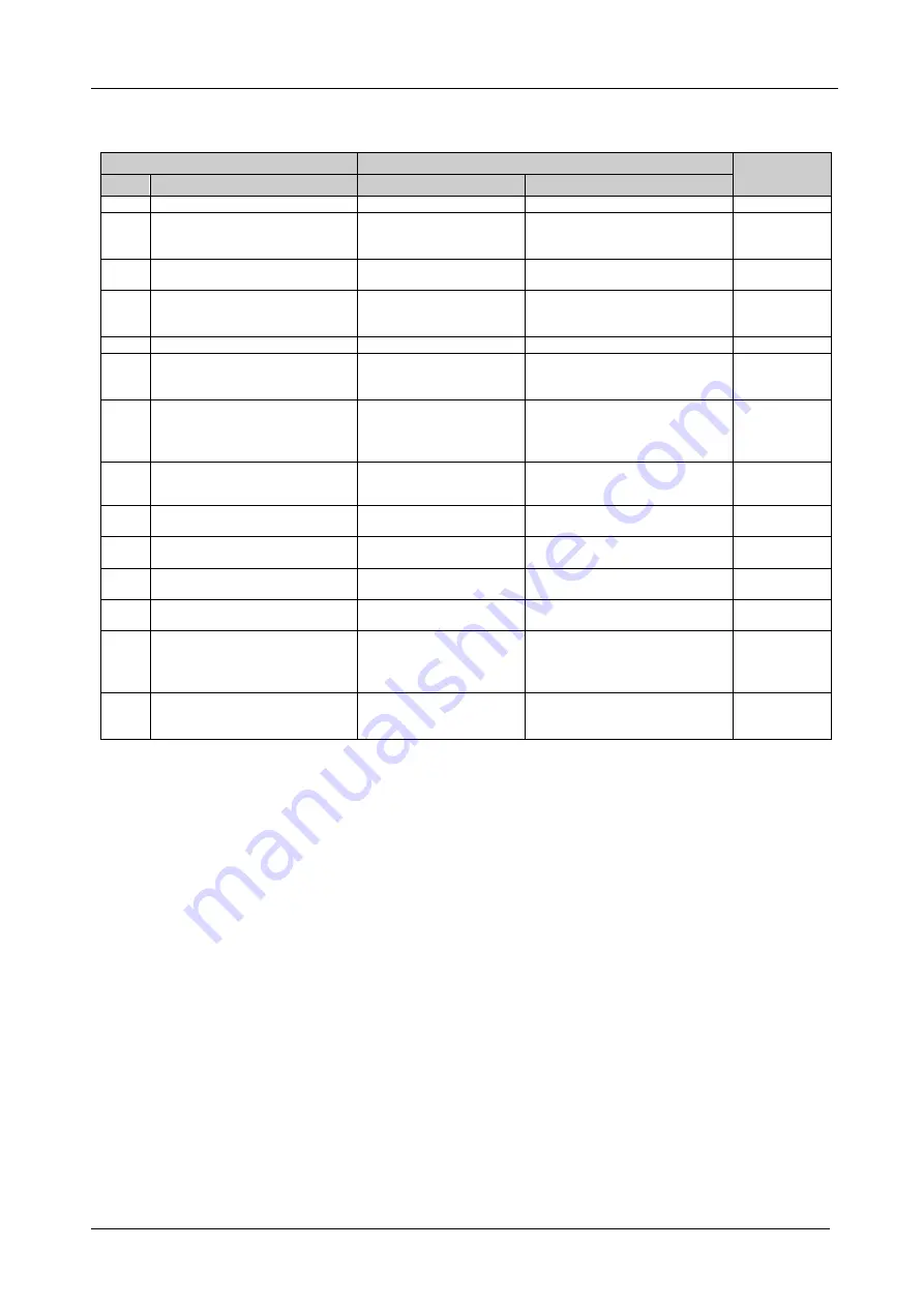
Table 10: Instruction Codes for Protocol 2000 

Note: All values in the table are decimal, unless otherwise stated. 

INSTRUCTION 

DEFINITION FOR SPECIFIC INSTRUCTION 

NOTE 

DESCRIPTION 

INPUT 

OUTPUT 

RESET  

SWITCH AUDIO 

Set equal to audio input 

which is to be switched 

(0 = disconnect) 

Set equal to audio output which 

is to be switched 

REQUEST STATUS OF AN 

AUDIO OUTPUT 

16 

ERROR / BUSY 

0 - error 
1 - invalid instruction 
2 - out of range 

9, 25 

18 

RESET AUDIO 

22 

SET AUDIO GAIN  

Equal to input number 

whose gain is to be set 

(0 = all) 

Set as parameter value 

2, 11, 24 

24 

INCREASE / DECREASE AUDIO 

GAIN 

Equal to input / output 

number whose parameter 
is to be increased / 
decreased  

6 - increase input 
7 - decrease input 
 

24 

25 

REQUEST AUDIO GAIN 

Equal to input number 

whose gain is requested 

24 

30 

LOCK FRONT PANEL 

0 - Panel unlocked 
1 - Panel locked 

31 

REQUEST WHETHER PANEL 

IS LOCKED 

16 

55 

REPLY ON 

0 - Off 
1 - On 

26 

57 

SET AUTO-SAVE 

I3 - no save 
I4 - auto-save                       

12, 2 

61 

IDENTIFY MACHINE  

2 - audio machine name 
4 - audio software version 
 

0 - Request first 4 digits 
1 - Request first suffix 
2 - Request second suffix 
10 - Request first prefix 

13 

62 

DEFINE MACHINE  

1 - number of inputs 
2 - number of outputs 
3 - number of setups 

1 - for video 
2 - for audio 
3 - for SDI 

14 

NOTES on the above table: 


NOTE 1

 – When the master switcher is reset, (e.g. when it is turned on), the reset code is sent to the PC. If this code is sent to 

the switchers, it will reset according to the present power-down settings. 
 

NOTE 2

 – These are bi-directional definitions. That is, if the switcher receives the code, it will perform the instruction; and if 

the instruction is performed (due to a keystroke operation on the front panel), then these codes are sent. For example, if the 
HEX code 
 

02  

85 

81  

83 

was sent from the PC, then the switcher (machine 3) switches input 5 to the output. If the user switched input 1 to the output 
via the front panel keypad, then the switcher sends HEX codes: 
 

42 

81 

81 

83 

to the PC. 
When the PC sends one of the commands in this group to the switcher, then, if the instruction is valid, the switcher replies by 
sending to the PC the same four bytes that it was sent (except for the first byte, where the DESTINATION bit is set high).   
 

NOTE 4

 – The reply to a "REQUEST" instruction is as follows: the same instruction and INPUT codes as were sent are 

returned, and the OUTPUT is assigned the value of the requested parameter. The reply to instruction 6 is as per the definitions 
in instruction 2. For example, if the present status of the output of machine number 5 is input 12, then the reply to the HEX 
code 
 

0B 

80 

81 

85 

would be HEX codes 
 

4B 

80 

8C 

85 


Summary of Contents for VS-121HCA

Page 1: ...Kramer Electronics Ltd USER MANUAL Model VS 121HCA 12 x 1 Stereo Audio S PDIF Switcher...

Page 2: ...Crossover Cable 12 7 4 2 Connecting the ETHERNET Port via a Network Hub Straight Through Cable 13 7 4 3 Configuring the Ethernet Port 13 7 5 Operating via the Infrared Remote Controller 13 7 5 1 Adjus...

Page 3: ...igure 10 Splash Screen 19 Figure 11 Atmel Flip Window 20 Figure 12 Device Selection Window 20 Figure 13 Device Selection Window 21 Figure 14 Loading the Hex 21 Figure 15 RS 232 Window 22 Figure 16 Atm...

Page 4: ...em adapter and rack ears 3 RC IR2 Infrared remote control transmitter including the required battery and a separate user manual4 This user manual4 2 Getting Started We recommend that you Unpack the eq...

Page 5: ...KRAMER SIMPLE CREATIVE TECHNOLOGY Getting Started 2 2 1 Quick Start This quick start chart summarizes the basic setup and operation steps...

Page 6: ...usted by IR remote control or RS 232 The volume settings are saved in non volatile memory The ability to operate it in tandem with the VS 121HC Operate the VS 121HCA using the front panel buttons or r...

Page 7: ...KRAMER SIMPLE CREATIVE TECHNOLOGY Your VS 121HCA Stereo Audio S PDIF Switcher 4 Figure 1 VS 121HCA 12 x 1 Stereo Audio S PDIF Switcher...

Page 8: ...IR receiver 1 11 RS 485 Terminal Block Port Pins B and A are for RS 485 Pin G may be connected to the shield if required 12 Setup DIP switches DIP switches for setup of the unit 1 to 4 are for settin...

Page 9: ...KRAMER SIMPLE CREATIVE TECHNOLOGY Installing the VS 121HCA in a Rack 6 5 Installing the VS 121HCA in a Rack This section provides instructions for rack mounting the unit...

Page 10: ...layer to the IN 10 terminal block connector 2 Connect the outputs to acceptors 1 or 2 output devices can be connected1 One S PDIF output acceptor for example a DAT recorder to the S PDIF OUT RCA conne...

Page 11: ...ee section 7 1 The RS 232 port see section 7 2 The RS 485 port see section 7 3 An Ethernet network see section 7 4 The RC IR2 remote control transmitter1 7 5 see section This section also describes Ho...

Page 12: ...hrough the RS 232 port For a description of the serial commands see section 11 To operate your device using serial commands you need to install Kramer s control software that can be downloaded from th...

Page 13: ...ethod A above only requires pins 2 3 and 5 to be connected you are free to decide whether to connect only these 3 pins or all 9 pins Figure 4 Straight Cable RS 232 Connection with a Null Modem Adapter...

Page 14: ...eration the RS 485 line must be terminated at both ends The master unit may be located at any part of the line but when it is at the end of the line the termination switch must be set ON To set line t...

Page 15: ...e VS 121HCA to the Ethernet port on your PC via a crossover cable with RJ 45 connectors This type of connection is recommended for identification of the factory default IP Address of the VS 121HCA dur...

Page 16: ...h RJ 45 connectors 7 4 3 Configuring the Ethernet Port After connecting the Ethernet port you must install and configure the port For detailed instructions on how to install and configure your Etherne...

Page 17: ...just the input volume on any of the individual input channels The setting is saved in non volatile memory and remains even after the unit is turned OFF and ON To adjust the volume 1 On the remote cont...

Page 18: ...connecting more than one VS 121HCA set the first machine only when connected via RS 232 to be machine number 1 The other VS 121HCA units must each be set to a unique machine number between 2 and 16 Ta...

Page 19: ...or the Ethernet ports of the VS 121HC To set the VS 121HCA to operate in tandem with the VS 121HC 1 Set the machine number on both units to 1 DIP switches 1 2 3 and 4 are set OFF 2 Connect the VS 121...

Page 20: ...AUDIO 2nd HARMONIC 0 02 1kHz POWER SOURCE 100 240V AC 50 60Hz 115V AC U S A 8VA DIMENSIONS 19 x 7 x 1U W D H rack mountable WEIGHT 2 6kg 8lbs approx ACCESSORIES Power cord null modem adapter rack ears...

Page 21: ...PC to the RS 232 port see section 9 1 2 Install the latest firmware see section 9 1 3 9 1 1 Downloading from the Internet To download the latest file1 1 Go to our Web site at from the Internet www kr...

Page 22: ...ng the Device Firmware To install the firmware perform the following steps 1 Double click the desktop icon Shortcut to FLIP EXE The Splash screen appears1 Figure 10 Splash Screen 2 After a few seconds...

Page 23: ...w by Pressing the keyboard shortcut key F2 or Choosing the Select command from the Device menu or Pressing the integrated circuit icon in the upper right corner of the window The Device Selection wind...

Page 24: ...Upgrading the VS 121HCA Firmware 21 AT89C51RD2 T89C51RD2 Figure 13 Device Selection Window 5 Click OK 6 From the File menu select Load Hex Figure 14 Loading the Hex...

Page 25: ...ication RS232 command from the Settings menu or press the keys Alt SCR The RS232 window appears 9 Change the COM port settings according to the configuration of your computer and select the 9600 baud...

Page 26: ...S 121HCA 14 If required disconnect the null modem adapter from the VS 121HCA 15 Press the FLASH PROG button on the front panel of the VS 121HCA outward to its original position see Figure 1 16 Power O...

Page 27: ...firmware file to a folder for example C Program Files KFR Upgrade 4 Install the KFR Programmer Application 9 2 2 Connecting the PC to the RS 232 Port To connect a PC to the RS 232 port of the VS 121H...

Page 28: ...lect the required COM Port1 3 Press the File button to select the s19 firmware file included in the package 4 Press the Send button to download the file The Send button lights red 5 Wait until the dow...

Page 29: ...4 02 84 81 81 IN 5 02 85 81 81 IN 6 02 86 81 81 IN 7 02 87 81 81 IN 8 02 88 81 81 IN 9 02 89 81 81 IN 10 02 8A 81 81 IN 11 02 8B 81 81 IN 12 02 8C 81 81 Table 8 VS 121HCA Increase Decrease Audio Gain...

Page 30: ...INSTRUCTION NO is the value to be set for N5 N0 2nd BYTE Bit 7 Defined as 1 I6 I0 INPUT When switching ie instruction codes 1 and 2 the INPUT 7 bits is set as the input number which is to be switched...

Page 31: ...ber of outputs 3 number of setups 1 for video 2 for audio 3 for SDI 14 NOTES on the above table NOTE 1 When the master switcher is reset e g when it is turned on the reset code is sent to the PC If th...

Page 32: ...ware version number Again the reply would be the decimal value of the INPUT and OUTPUT the INPUT representing the number in front of the decimal point and the OUTPUT representing the number after it F...

Page 33: ...er lightning orotheractsofnature ii Product modification orfailureto followinstructions supplied with theproduct iii Repairorattemptedrepairby anyonenot authorized byKramer iv Anyshipment oftheproduct...

Page 34: ...or the latest information on our products and a list of Kramer distributors visit our Web site www kramerelectronics com where updates to this user manual may be found We welcome your questions commen...

Reviews: