background image


VP-435 - Operating the VP-435


11 


Mode 

Function 

AUTO INPUT 
SCAN 

Selects automatic input scan (default OFF) 
When ON, after power up, the 

VP-435

 switches to the last selected input. If 

there is no signal present at this input, the 

VP-435

 scans through the inputs 

(cycling through HDMI>UXGA>COMP) the LED of the detected input flashes. 
When selecting an input via the front panel or Remote IR transmitter, the 

VP-

435

 switches to that input. If a signal is not detected within 30 seconds, the 

VP-435

 starts scanning through the inputs until it finds a valid input 

EXIT 

Select to exit the menu 
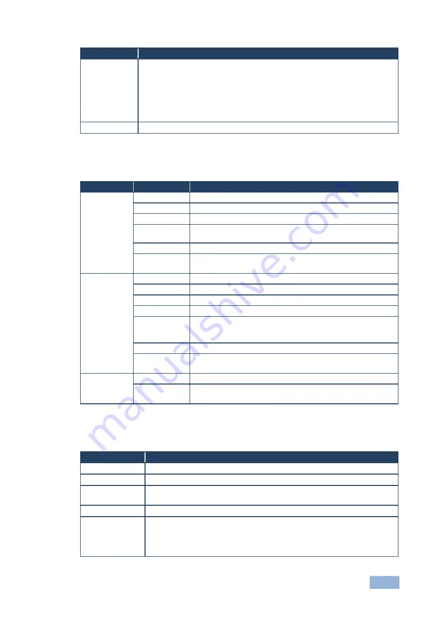
5.2.2 

The FINETUNE Menu 

The following defines the Finetune menu. 

Input Signal 

Parameter 

Function  

COMPONENT 

HUE 

Sets the color hue  

SATURATION 

Sets the color saturation  

SHARPNESS 

Sets the sharpness of the picture 

NOISE 
REDUCTION 

Selects the noise reduction level: OFF, HI, LOW and MID (middle) 

COLOR FILTER  Set to ON to enable color filtering 

DROP LINES 

Set to ON to crop lines at the bottom of the picture (to remove 
visible data generated by DVD players, for example)


VGA 

PHASE 

Sets the clock phase 

CLOCK 

Sets the clock frequency 

H-POSITION 

Sets the horizontal position of the picture 

V-POSITION 

Sets the vertical position of the picture 

AUTO TUNE 

When set to ON, auto adjusts the image (centers it correctly on the 
screen) every time the input is switched to VGA or when the input 
resolution changes  

COLOR FILTER  Set to ON to enable color filtering 

DROP LINES 

Set to ON to crop lines at the bottom of the picture (to remove 
visible data generated by DVD players, for example)


HDMI 

COLOR FILTER  Set to ON to enable color filtering 

DROP LINES 

Set to ON to crop lines at the bottom of the picture (to remove 
visible data generated by DVD players, for example)


5.2.3 

The OSD Menu 

The following defines the OSD menu. 

Parameter 

Function  

H POSITION 

Sets the horizontal position of the OSD (from 0 to 100) 

V POSITION  

Sets the vertical position of the OSD (from 0 to 100) 

TIMER 

Sets the timeout period in seconds (from 5 to 100). The default timeout is 10 
seconds 

BACKGROUND 

Sets the OSD background between 0 (solid black) and 8 (transparent) 

DISPLAY 

Select the information shown on the screen during operation: 

ON

 - the information is shown permanently  

OFF 

- the information is not shown  

INFO

 - the information is shown for a few seconds 

Summary of Contents for VP-435

Page 1: ...KRAMER ELECTRONICS LTD USER MANUAL MODEL VP 435 Component UXGA HDMI Scaler P N 2900 000262 Rev 13...

Page 2: ......

Page 3: ...P 435 6 4 1 Connecting the Remote Terminal Block 7 5 Operating the VP 435 9 5 1 Using the Front Panel Buttons 9 5 2 Using the CONTROL Buttons 9 5 3 Using the IR Remote Control Transmitter 12 6 Technic...

Page 4: ...n 11 groups that are clearly defined by function GROUP 1 Distribution Amplifiers GROUP 2 Switchers and Routers GROUP 3 Control Systems GROUP 4 Format Standards Converters GROUP 5 Range Extenders and R...

Page 5: ...the best performance Use only good quality connection cables we recommend Kramer high performance high resolution cables to avoid interference deterioration in signal quality due to poor matching and...

Page 6: ...WEEE Directive 2002 96 EC aims to reduce the amount of WEEE sent for disposal to landfill or incineration by requiring it to be collected and recycled To comply with the WEEE Directive Kramer Electron...

Page 7: ...nel selector button Other resolutions can be selected via the OSD menu Has analog audio inputs for the COMP UXGA and HDMI inputs Automatically detects and selects the audio source for the HDMI input D...

Page 8: ...cts to the HDMI acceptor 11 HDMI IN 3 5mm Mini Jack Connector Connects to the analog unbalanced stereo audio signal The audio source is automatically detected and selected The default selection is the...

Page 9: ...Y Pb Pr RCA connectors and to the COMP In L and R audio RCA connectors 2 Connect a computer graphics source to the UXGA In 15 pin HD connector and to the UXGA In audio 3 5mm mini jack connector 3 Conn...

Page 10: ...way to the Input selector button Using the contact closure remote control also known as push to make momentary contact you can select the HDMI the COMP or the UXGA input To do so momentarily connect...

Page 11: ...8 VP 435 Connecting the VP 435 Figure 3 Connecting the Contact Closure Remote Control PINs...

Page 12: ...NPUT UXGA COMP or HDMI A desired RESOLUTION Res A control operation using the MENU ENTER and buttons 5 2 Using the CONTROL Buttons The CONTROL buttons let you control the VP 435 via the OSD menu Press...

Page 13: ...edded audio on the HDMI input is selected for an HDMI signal or the analog audio input is selected if the HDMI input does include embedded audio for example for a DVI input signal EMBEDDED In this cas...

Page 14: ...GA PHASE Sets the clock phase CLOCK Sets the clock frequency H POSITION Sets the horizontal position of the picture V POSITION Sets the vertical position of the picture AUTO TUNE When set to ON auto a...

Page 15: ...lution to SVGA XGA Sets the output resolution to XGA SXGA Sets the output resolution to SXGA UXGA Sets the output resolution to UXGA 1080i Sets the output resolution to 1080i 480p Sets the output reso...

Page 16: ...GA SXGA UXGA 480i 480p 1600x900 OUTPUT REFRESH RATE 60Hz for computer graphics resolutions 50 60Hz for HDTV resolutions PROCESSING DELAY 30ms approx CONTROLS Front panel buttons contact closure and in...

Page 17: ......

Page 18: ...it our Web site where updates to this user manual may be found We welcome your questions comments and feedback Web site www kramerelectronics com E mail info kramerel com P N 2900 000262 Rev 13 SAFETY...

Reviews: