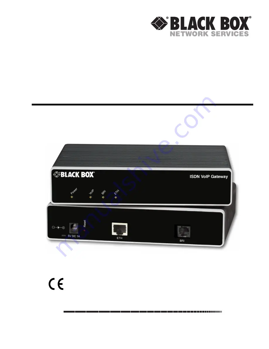
background image


VOE102


ISDN VoIP Gateway


Getting Started Guide


Important


This is a Class A device and is intended for use in a light industrial  environment. It is not intended nor approved for use in an industrial  
or residential environment.

CUSTOMER

SUPPORT

INFORMATION

Order toll-free in the U.S. 24 hours, 7 A.M. Monday to midnight Friday: 877-877-BBOX
FREE technical support, 24 hours a day, 7 days a week: Call 724-746-5500 or fax 724-746-0746
Mail order: Black Box Corporation, 1000 Park Drive, Lawrence, PA  15055-1018
Web site: www.blackbox.com • E-mail: [email protected]

Summary of Contents for VOE102

Page 1: ...for use in an industrial or residential environment CUSTOMER SUPPORT INFORMATION Order toll free in the U S 24 hours 7 A M Monday to midnight Friday 877 877 BBOX FREE technical support 24 hours a day 7 days a week Call 724 746 5500 or fax 724 746 0746 Mail order Black Box Corporation 1000 Park Drive Lawrence PA 15055 1018 Web site www blackbox com E mail info blackbox com ...

Page 2: ... cables try to correct the interference by one or more of the following measures moving the computing equipment away from the receiver re orienting the receiving antenna and or plugging the receiving equipment into a different AC outlet such that the computing equip ment and receiver are on different branches ISDN Connection The device identified in this document is not intended nor approved for c...

Page 3: ...ocación del aparato eléctrico sobre una cama sofá alfombra o superficie similar puede bloquea la ventilación no se debe colocar en libreros o gabinetes que impidan el flujo de aire por los orificios de ventilación 10 El equipo eléctrico deber ser situado fuera del alcance de fuentes de calor como radiadores registros de calor estufas u otros aparatos incluyendo amplificadores que producen calor 11...

Page 4: ...r o el contacto ha sido dañado o B Objectos han caído o líquido ha sido derramado dentro del aparato o C El aparato ha sido expuesto a la lluvia o D El aparato parece no operar normalmente o muestra un cambio en su desempeño o E El aparato ha sido tirado o su cubierta ha sido dañada ...

Page 5: ...ents 1 General information 14 2 Applications overview 18 3 VOE installation 21 4 VOE initial configuration 26 A Specifications 36 B Cabling 40 C Port pin outs 43 D VOE factory configuration 45 E End user license agreement 49 ...

Page 6: ...nals to an Internet Telephony Service Provider ITSP 19 ISDN telecommuter connection to a PBX via a corporate private network 20 3 VOE installation 21 Installing the VOE 22 Placing the VOE 22 Installing cables 22 Connecting the VOE to the ISDN terminals 23 Connecting the VOE to the IP network 23 Connecting the VOE to the power supply 24 External S Bus power supply 25 4 VOE initial configuration 26 ...

Page 7: ...38 Management 39 Operating environment 39 Operating temperature 39 Operating humidity 39 System 39 Dimensions 39 Weight and power dissipation 39 B Cabling 40 Introduction 41 Ethernet 41 ISDN BRI 42 C Port pin outs 43 Introduction 44 Ethernet 44 ISDN BRI Terminal NT Net port 44 D VOE factory configuration 45 Introduction 46 E End user license agreement 49 End User License Agreement 50 1 Definitions...

Page 8: ...xtension to home office 20 6 Connecting to an ISDN terminal 23 7 Connecting the VOE to the network via a hub or switch 24 8 Router Power LED 25 9 VOE Discovery Tool window 27 10 VOE home page 28 11 Main GUI elements 29 12 WAN page 31 13 Typical Ethernet straight through cable diagram 41 14 Connecting an ISDN device 42 ...

Page 9: ...9 List of Tables 1 General conventions 13 2 Rear panel ports 16 3 VOE102 LED definitions 17 4 VOE weight and maximum power specifications 39 5 RJ 45 Ethernet socket 44 6 RJ 45 BRI NT Net socket 44 ...

Page 10: ...on and applications Chapter 3 on page 21 provides hardware installation procedures Chapter 4 on page 26 provides quick start procedures for configuring the VOE router Appendix A on page 36 contains specifications for the routers Appendix B on page 40 provides cable recommendations Appendix C on page 43 describes the router s ports and pin outs Appendix D on page 45 lists the factory configuration ...

Page 11: ...T heading calls attention to important information The alert symbol and CAUTION heading indicate a potential haz ard Strictly follow the instructions to avoid property damage The shock hazard symbol and CAUTION heading indicate a potential electric shock hazard Strictly follow the instructions to avoid property damage caused by electric shock The alert symbol and WARNING heading indicate a potenti...

Page 12: ...t incorpo rates a disconnect device and shall be positioned within easy reach of the operator The mains outlet shall be within 10 feet 3 meters of the device shall be easily accessible and protected by a circuit breaker Hazardous network voltages are present in WAN ports regardless of whether power to the VOE is ON or OFF To avoid electric shock use caution when near WAN ports When detaching cable...

Page 13: ...talic type Parts of commands which are related to elements already named by the user are in boldface italic font Italicized Futura type Variables for which you supply values are in italic font Futura type Indicates the names of fields or windows Garamond bold type Indicates the names of command buttons that execute an action Angle brackets indicate function and keyboard keys such as SHIFT CTRL C a...

Page 14: ...14 Chapter 1 General information Chapter contents VOE102 overview 15 VOE102 rear panel 16 VOE102 front panel 17 ...

Page 15: ... ISDN S0 S T Basic Rate Interface BRI that delivers high quality Voice over IP VoIP to ISDN terminals connected directly or via a residential S bus A 10 100 Base T Ethernet port pro vides connection to either 1 an Internet Telephony Service Provider ITSP via a broadband access router and xDSL or cable modem or 2 a remote IP PBX over a corporate private network Figure 1 VOE102 The VOE102 performs t...

Page 16: ...to an ISDN phone or PBX TE port Config urable as point to point or point to multipoint 5V DC 1 0A The VOE102 has a 5V DC 1A power input see figure 2 Reset The reset button see figure 2 has three functions Restart the unit with the current startup configuration Press for less than 1 second and release the Reset button to restart the unit with the current startup configuration Restart the unit with ...

Page 17: ...ndicates the gateway is registered to an H 323 gatekeeper SIP server or in the case of direct routing has at least one active VoIP connection Off indicates the unit is not configured or registered or has no active direct routed VoIP connection Flashing green indicates that the unit is attempting to register or has failed to register BRI Off indicates no active calls Blinking when one or two B chan...

Page 18: ...pter 2 Applications overview Chapter contents Introduction 19 Connect ISDN terminals to an Internet Telephony Service Provider ITSP 19 ISDN telecommuter connection to a PBX via a corporate private network 20 ...

Page 19: ... ISDN and SIP H 323 signaling schemes In the corporate private network intelligent and configurable call routing supports existing numbering plans for ultimate useability Note Detailed configuration information for the applications can be found on the CD ROM that was included with your VOE device or online from the Black Box webserver at www blackbox com Connect ISDN terminals to an Internet Telep...

Page 20: ... at the corporate headquarters The VOE routes the ISDN calls through the corporate private network see figure 5 using Voice over IP so a home user avoids toll charges when making calls to headquarters Remote users can make and receive calls as though located in the main office with all the calling features and services available to call ers connected directly to the PBX such as station to station ...

Page 21: ...apter contents Installing the VOE 22 Placing the VOE 22 Installing cables 22 Connecting the VOE to the ISDN terminals 23 Connecting the VOE to the IP network 23 Connecting the VOE to the power supply 24 External S Bus power supply 25 ...

Page 22: ...to the cables The unit should be installed in a dry environment with sufficient space to allow air circulation for cooling Note For proper ventilation leave at least 2 inches 5 cm to the left right front and rear of the unit Installing cables Connect the cables in the following order 1 Connect the ISDN terminal to the BRI port see section Connecting the VOE to the ISDN terminals on page 23 2 Conne...

Page 23: ...ower to any connected terminals For details on the BRI port pinout and ISDN cables refer to Appendix B Cabling on page 40 and Appendix C Port pin outs on page 43 Connecting the VOE to the IP network The VOE comes with a 10 100 Base Tx Ethernet port for connection to an IP network The Ethernet WAN interface is factory configured as a DHCP client so you must connect the VOE to an IP network that pro...

Page 24: ...ix B Cabling on page 40 and Appendix C Port pin outs on page 43 Connecting the VOE to the power supply 1 Insert the barrel type connector end of the AC power supply into the 5V DC 1 0A port see figure 2 on page 16 2 Verify that the AC power cord included with your router is compatible with local standards 3 Connect the male end of the AC power supply power cord to an appropriate AC power outlet Th...

Page 25: ... power supplies for ISDN terminals connected to the VOE The VOE supplies S Bus line power to ISDN terminals connected to the BRI port so external power supplies are not required for the ISDN terminals Congratulations you have finished installing the VOE Now go to chapter 4 VOE initial configuration on page 26 ISDN VoIP Gateway Pow er VoIP BR I ETH IS DN VoIP Gateway Po we r Vo IP BR I ET H Power L...

Page 26: ...ry Tool 27 2 Access the Web Browser GUI Interface 27 3 Configuring your VOE 30 Accessing the Internet 30 Bootloader 32 Start Bootloader 32 Start up with factory configuration 33 Load a new application image VOE Firmware via TFTP 33 Load a new application image VOE Firmware via the serial link 35 ...

Page 27: ...ool identifies any Black Box VoIP devices installed on your network and displays the model number IP address and MAC address of each unit To use the discovery tool do the following 1 Insert the CD included with your VOE into the CD drive on your PC 2 Copy the file named VOEDiscovery exe from the CD to your PC Figure 9 VOE Discovery Tool window 3 At your PC double click the SNDiscovery exe file nam...

Page 28: ...ow 3 Enter the username administrator Do not enter a password Instead simply click OK Your web browser will display the VOE home page see figure 10 Figure 10 VOE home page The VOE home page displays three action buttons that allow you to store the current configuration state reload the device and restore to factory defaults The home page also displays certain basic system information You can alway...

Page 29: ...edge presents you with a menu listing giving access to the various configu ration and status pages of the VOE At the top of the page you see the Current System Path which displays the location and element currently presented in the main area The rest of the page displays the configuration and status information for the different features of the VOE Navigation bar Current system path Configuration ...

Page 30: ... NOT PER MANENTLY SAVED in non volatile memory RAM To survive power failure or manual reload you must store your new settings in non volatile memory To save your changes return to the home page and press the Save Current Configuration button For each box containing an Apply button fill in the required fields and press apply once The settings are applied immediately after the button is pressed If t...

Page 31: ...thernet connections should be made to access the Internet immedi ately PPPoE The VOE establishes the connection with the Internet using PPPoE This is most commonly used when the VOE is connected to a DSL bridge or a DSL router that is configured in bridge mode most rout ers are capable of this Enter the DSL credentials username and password on the VOE and click the Apply icon User Defined Address ...

Page 32: ...ia the serial link of the console Start Bootloader To start the Bootloader power on the VOE while pressing the reset button Open a Telnet session to the VOE via one of the Ethernet interfaces or open a CLI session via the console port if available on the VOE The login display will appear Using the credentials admin black box log in to the VOE The following prompt will be displayed RedBoot Type hel...

Page 33: ...d to receive the new application image mask_len is the length of the network address or the number of 1 s within the subnet mask See Note below 2 optional RedBoot ip_address g gateway Sets the IP address of the default gateway 3 optional RedBoot ping h tftp server_ip_address Tests the connectivity to the TFTP server 4 RedBoot load r v h host b base_address file_name Downloads an application image ...

Page 34: ...e RedBoot ip l 172 16 40 98 19 RedBoot ip g 172 16 32 1 RedBoot ping h 172 16 32 100 Network PING from 172 16 40 98 to 172 16 32 100 PING received 10 of 10 expected RedBoot load r v h 172 16 32 100 b 0x1800100 Sn4xxx image bin Using default protocol TFTP Raw file loaded 0x01800100 0x0199ca6b 1689964 bytes assumed entry at 0x01800100 RedBoot fis delete n 1 Delete image 1 continue y n y Erase from 0...

Page 35: ...odem or ymodem Specify the protocol to be used X Modem or Y Modem base_address memory location where to store the application image Use the default address 0x1800100 Execute the above RedBoot command first then start the trans fer from the terminal program with the command Send file via X Modem or similar 5 RedBoot fis delete n 1 Deletes the first application image Reply with y to the confirmation...

Page 36: ...ectivity 37 Voice processing signalling dependent 37 Fax and modem support 37 Voice signalling 38 Voice routing session router 38 IP services 38 Management 39 Operating environment 39 Operating temperature 39 Operating humidity 39 System 39 Dimensions 39 Weight and power dissipation 39 ...

Page 37: ...tosensing auto MDX Voice processing signalling dependent 2 full duplex channels of Voice CODECS G 711 A Law µ Law 64 kbps G 726 ADPCM 40 32 24 16 kbps G 723 1 6 3 kbps G 729ab 8 kbps Transparent ISDN data G 168 echo cancellation DTMF detection and generation Carrier tone detection and generation Silence suppression and comfort noise Configurable dejitter buffer Configurable tones dial ringing busy...

Page 38: ...led party number Time of day day of week date ISDN bearer capability Various other information elements IEs of the ISDN setup Wildcard and regular expression matching Number manipulation functions Replace numbers Add remove digits Pattern matching and replacement IP services DiffServe ToS set or queue per header bits 802 1p VLAN tagging IPSEC AH ESP Modes Manual Key IKE optional AES DES 3DES Encry...

Page 39: ...MIB Built in diagnostic tools trace debug Operating environment Operating temperature 32 104 F 0 40 C Operating humidity 5 80 non condensing System CPU Motorola MC870 operating at 66 MHz Memory 16 Mbytes SDRAM 4 Mbytes Flash Dimensions 6W x 1 5H x 7 25D in 4H x 15 5W x 18 5D cm Weight and power dissipation See table 4 Table 4 VOE weight and maximum power specifications Model Weight Maximum power d...

Page 40: ...40 Appendix B Cabling Chapter contents Introduction 42 Ethernet 42 ISDN BRI 43 ...

Page 41: ... to third party products Ethernet Ethernet devices 10Base T 100Base T are connected to the VOE over a cable with RJ 45 plugs All Ethernet ports on the VOE are Auto MDX and use any straight or crossover cable to connect to hubs switches PCs or other devices Figure 13 Typical Ethernet straight through cable diagram Hub RJ 45 male 1 2 3 6 RJ 45 male 1 2 3 6 Straight through cable Note Other pins are ...

Page 42: ... terminals phones PBXs or an ISDN S BUS using cables terminated with RJ 45 connectors Use straight though cables to connect to the TE port of your phone PBX or residential S BUS Figure 14 Connecting an ISDN device Note Other pins are not used ISDN Phone RJ 45 male RJ 45 male 3 4 5 6 3 4 5 6 ...

Page 43: ...43 Appendix C Port pin outs Chapter contents Introduction 45 Ethernet 45 ISDN BRI Terminal NT Net port 45 ...

Page 44: ...rts of the VOE Ethernet Note Pins not listed are not used ISDN BRI Terminal NT Net port The BRI terminal port uses an 8 pin RJ 45 connector the pinout is shown in table 6 Note Pins not listed are not used Table 5 RJ 45 Ethernet socket Pin Signal 1 TX 2 TX 3 RX 6 RX Table 6 RJ 45 BRI NT Net socket Pin Signal 3 Rx 4 Tx 5 Tx 6 Rx ...

Page 45: ...45 Appendix D VOE factory configuration Chapter contents Introduction 47 ...

Page 46: ... deny 1 tcp any any eq 23 deny 2 tcp any any eq 80 deny 3 udp any any eq 161 permit 4 ip any any profile call progress tone US_DIAL_TONE play 1 0 350 13 440 13 profile call progress tone US_RB_TONE play 1 2000 440 19 480 19 pause 2 4000 profile call progress tone US_BUSY_TONE play 1 500 480 24 620 24 pause 2 500 profile call progress tone US_CONGESTION_TONE play 1 250 480 24 620 24 pause 2 250 pro...

Page 47: ...IAL route T dest table RT_NR_BLOCKING MT_SPEED_DIAL routing table called e164 RT_NR_BLOCKING route default dest table RT_CALL_ROUTING MT_SET_CNPN routing table called e164 RT_CALL_ROUTING route default dest interface IF_SIP_SERVICE routing table called e164 RT_INCOMING route default dest interface IF_S0_00 MT_NR_TRANSLATION mapping table called e164 to called e164 MT_SPEED_DIAL mapping table calli...

Page 48: ... sip GW_SIP no shutdown port ethernet 0 0 bind interface IF_IP_WAN router medium auto pppoe session SES_PPPOE bind subscriber SUB_PPPOE shutdown port ethernet 0 0 no shutdown port bri 0 0 clock auto encapsulation q921 q921 protocol pmp uni side auto encapsulation q931 q931 protocol dss1 uni side net encapsulation cc isdn bind interface IF_S0_00 switch port bri 0 0 no shutdown ...

Page 49: ...49 Appendix E End user license agreement Chapter contents End User License Agreement 51 1 Definitions 51 2 Title 51 3 Term 51 4 Grant of License 51 5 Warranty 51 6 Termination 52 7 Other licenses 52 ...

Page 50: ...gnated Equipment at a site owned or leased by the End User B The End User may copy licensed Program s as necessary for backup purposes only for use with the Des ignated Equipment that was first purchased or used or its temporary or permanent replacement C The End User is prohibited from disassembling decompiling reverse engineering or otherwise attempt ing to discover or disclose the Program s sou...

Page 51: ...nate this Agreement should End User violate any of the provisions of section 4 Grant of License on page 50 C Upon termination for A or B above or the end of the Term End User is required to destroy all copies of the licensed Program s 7 Other licenses The Program may be subject to licenses extended by third parties Accordingly Black Box licenses the Pro grams subject to the terms and conditions di...

Reviews: