


Your VP-1608 16x8 RGBHV/Balanced Audio Matrix
5
5
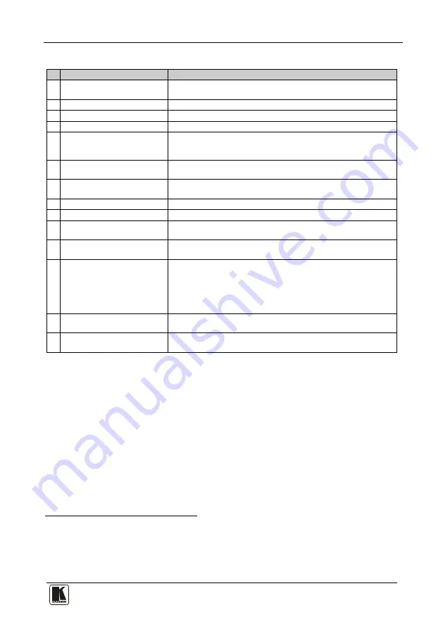
Table 1: Front Panel VP-1608 16x8 RGBHV/Balanced Audio Matrix Features
#
Feature
Function
1
IR
Receiver
The red LED is illuminated when receiving signals from the Kramer
Infra-red remote control transmitter
2
POWER
Switch
Illuminated switch supplying power to the unit
3
OUTPUT
SELECTOR
Buttons Select the output to which the input is switched (from 1 to 8)
4
INPUT SELECTOR
Buttons
Select the input to switch to the output (from 1 to 16)
5
OFF
Button
Pressing
OFF
after pressing an
OUTPUT
button disconnects that
output from the inputs. To disconnect all the outputs, press the
ALL
button and then the
OFF
button
6
ALL
Button
Pressing
ALL
followed by an
INPUT
button, connects that input to
all outputs
7
TAKE
Button
Pressing
TAKE
toggles the mode between the
CONFIRM
mode
8
and the
AT ONCE
mode (user confirmation per action is unnecessary)
VIDEO
Button
When pressed actions relate to video
9
AUDIO
Button
When pressed actions relate to audio
10
AFV
Button
When pressed audio channels follow the video channels. The button
is illuminated when the
AFV
mode is selected
11
STO
Button
Pressing STO (STORE) followed by an input button stores the
current setup
12
RCL
Button
Pressing the
RCL
(
RECALL
) button and the corresponding input
button recalls a setup
After pressing the button, the stored status flashes. Pressing a
different input button lets you view
13
your choice, pressing the
RCL
button again implements the new
status
LOCK
Button
Pressing the
LOCK
button for more than 2 seconds,
engages/disengages the front panel switches
14
INPUT STATUS
7-segment
Display
Displays the selected input switched to the output (marked above
each input)
1 The INPUT SELECTOR buttons are also used to store/recall the input/output configurations (refer to section 8.4)
2 For example, press ALL and then INPUT button # 2 to connect input # 2 to all the outputs
3 When in Confirm mode, the TAKE button illuminates
4 Only view, nothing is implemented at this stage
5 Also displays the number included in the product name and the firmware version number, as section 8.8 describes


