background image

KRAMER:  SIMPLE CREATIVE TECHNOLOGY


Configuring the VP-728 via the OSD MENU Screens 


26 

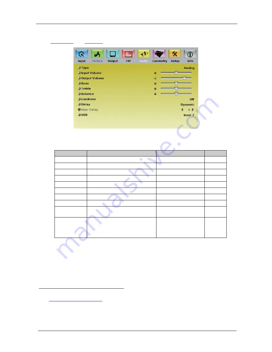
8.5 The Audio Screen 

Figure 13

 and 

Table 9

 define the Audio screen.  


Figure 13: Audio Screen 

Table 9: Audio Screen Functions

1


Setting 

Function 

Selection/Range 

Default 

Type 

Select the audio input type

2

Analog or S/PDIF 


Analog 

Input Volume 

Adjust the input volume 

-22 to 22 

Output Volume  Adjust the output volume 

-100 to 24 

Bass 

Adjust the bass  

-36 to 36 

Treble 

Adjust the treble  

-36 to 36 

Balance  

Adjust the balance  

-10 to 10 

Loudness  

Set the loudness 

On/Off 

Off  

Delay 

Define the delay type  

Dynamic or User Define  Dynamic

3

User Delay 


Available when selecting the User 

Defined delay 

0 to 340

4

 (msec) 

USB 

Select the audio signal to follow the 

USB signal  

No Audio, Input 1, Input 

2, Input 3, Input 4, VGA 

1, VGA 2, HDMI 1 or 

HDMI 2 

No Audio 


1 Values may change according to the firmware version (you can download the up-to-date firmware version from our Web 
site at 

http://www.kramerelectronics.com

2 Available for IN 1 to IN 4 
3 Dynamic means that the audio delay is equal to the pipeline video delay 
4 In 2msec steps 

Summary of Contents for ProScale VP-728

Page 1: ...Kramer Electronics Ltd USER MANUAL Model VP 728 Presentation Switcher Scaler...

Page 2: ...nt Panel Buttons 16 7 3 Locking and Unlocking the Front Panel 18 7 4 The Infrared Remote Control Transmitter 18 8 Configuring the VP 728 via the OSD MENU Screens 20 8 1 The Input Screen 21 8 1 1 Readi...

Page 3: ...re 20 RS 232 PINOUT Connection 37 Figure 21 Splash Screen 38 Figure 22 Atmel Flip Window 39 Figure 23 Device Selection Window 39 Figure 24 Selecting the Device Window 40 Figure 25 Loading the Hex 40 F...

Page 4: ...ns of the RGBHV RGBS PC RGsB PC Input Signal 44 Table 22 Technical Specifications of the HDMI Input Signal for RGB Colorspace 44 Table 23 Technical Specifications of the Y C Video Signal 45 Table 24 T...

Page 5: ...728 Presentation Switcher Scaler Infrared remote control transmitter 2 sets of C SF 2RVM cables power cord2 This user manual rack ears and null modem adapter 3 2 Getting Started We recommend that you...

Page 6: ...KRAMER SIMPLE CREATIVE TECHNOLOGY Getting Started 2...

Page 7: ...display never glitches K IIT XL Picture in Picture Image Insertion Technology ultra stable picture in picture picture and picture and split screen capability Any video source can be inserted into or...

Page 8: ...be located anywhere on the screen4 In addition the VP 728 Includes non volatile memory that retains the last settings after switching the power off and then on again Digitally reprocesses the signal t...

Page 9: ...patible with DVI Digital Visual Interface and user friendly connector Supports two way communication between the video source such as a DVD player and the digital television enabling new functionality...

Page 10: ...erference deterioration in signal quality due to poor matching and elevated noise levels often associated with low quality cables Avoid interference from neighboring electrical appliances and position...

Page 11: ...Your Presentation Switcher Scaler 7 Figure 1 VP 728 Presentation Switcher Scaler Front Panel Figure 2 VP 728 Presentation Switcher Scaler Rear Panel...

Page 12: ...ggle 13 ENTER Button Moves to the next level in the OSD screen or accepts a new parameter 14 Button Decreases the range by one step in the OSD screen or moves to the previous level in the OSD screen D...

Page 13: ...eo analog audio source 1 29 UXGA 2 Connects to the unbalanced stereo analog audio source 2 30 AUDIO OUT RCA Connectors L Connect to the left unbalanced stereo analog audio acceptor 31 R Connect to the...

Page 14: ...KRAMER SIMPLE CREATIVE TECHNOLOGY Installing in a Rack 10 5 Installing in a Rack This section describes what to do before installing in a rack and how to rack mount...

Page 15: ...RCA connector The audio of the s Video source 4 to the AUDIO UNIV IN 4 L and R RCA connector The audio of computer graphics source to the AUDIO UXGA 1 3 5mm mini jack 3 Connect the video outputs The H...

Page 16: ...er Scaler 12 5 Connect the power cord1 Figure 3 the power connector is not illustrated in 6 If required connect a PC via RS 232 see section 6 1 Figure 3 Connecting the VP 728 Rear Panel 1 We recommend...

Page 17: ...Connecting your Presentation Switcher Scaler 13 6 1 Connecting a PC Figure 4 Connecting to a PC via RS 232...

Page 18: ...ent video and graphic sources simultaneously2 An inserted video source You can display 3 PIP over a graphic source4 An inserted graphic source4 PIP over a video source3 Three types of PIP insertions a...

Page 19: ...the PIP Source To use the PIP feature set the PIP source via the OSD menu see Figure 12 and Table 8 or the remote transmitter keys To set the PIP source via the OSD menu do the following 1 Press the M...

Page 20: ...me category as the background source for example video on video which is not compliant to Table 3 a message is prompted unavailable operation To replace a PIP in the same category for example changing...

Page 21: ...Input 3 Video No No Yes No No Yes No No No No No Yes Yes Yes Yes Yes No YC No No Yes No No Yes No No No No No Yes Yes Yes Yes Yes No Comp Yes Yes No Yes Yes No No No No Yes Yes No No No No No No Input...

Page 22: ...el is locked and the PANEL LOCK button is illuminated Pressing a button will have no effect To unlock the VP 728 Press the illuminated PANEL LOCK button on the front panel The front panel unlocks and...

Page 23: ...u Navigation arrows Allows maneuvering within an OSD screen left right up and down as well as the ENTER arrow at the center The and buttons increase and decrease the volume level respectively when not...

Page 24: ...o display the main MENU screen1 Figure 8 which displays eight interactive icons see Press the MENU front panel OSD button or the MENU key on the infrared remote control transmitter to move to the prev...

Page 25: ...to the input resolution V Position Set the vertical position Set according to the input resolution Frequency Adjust the frequency7 0 to 50 0 Phase Adjust the phase 0 to 31 0 Auto image Assesses the im...

Page 26: ...G files 1 Load the JPEG2 2 Connect the Memory stick to the USB connector on the front panel images to the route directory of a USB memory stick 3 Select the USB INPUT button on the front panel 4 Selec...

Page 27: ...a Gamma 1 to Gamma 5 Gamma 1 Film Mode Set the film mode Auto Video Film Auto Temporal NR Set the temporal noise reduction level Off Low Medium High High Mosquito NR Set the Mosquito noise reduction l...

Page 28: ...etterbox Follow Output7 Virtual Wide Follow Input8 Follow Output or Custom H Pan 9 Horizontal pan 16 to 16 0 V Pan9 Vertical pan 16 to 16 0 H Zoom9 Horizontal zoom 8 to 8 0 V Zoom9 Vertical zoom 8 to...

Page 29: ...Set the horizontal position of the PIP on the display 0 128 3 V Position Set the vertical position of the PIP on the display 0 128 0 H Size Set custom size6 1 256 V Size Set custom size6 1 256 Frame...

Page 30: ...djust the treble 36 to 36 0 Balance Adjust the balance 10 to 10 0 Loudness Set the loudness On Off Off Delay Define the delay type Dynamic or User Define Dynamic3 User Delay Available when selecting t...

Page 31: ...t or Reset to reset diagonal projections settings Top Left Pincushion Barrel Adjust the pincushion or barrel appearance of the screen 20 to 20 0 Rotation Rotate the display by 180 degrees clockwise or...

Page 32: ...UXGA inputs is selected or if the UXGA input resolution has changed Manual Auto Manual Switching Mode Select seamless switching fade through Black or Fast switching which is faster but may cause glit...

Page 33: ...Connect the Memory stick to the USB connector on the front panel 4 Select the USB INPUT button on the front panel The slideshow begins at the set speed You have to set the slideshow parameters before...

Page 34: ...0x60Hz 1680x1050x60Hz 1400x1050x60Hz Mode 2 1 Set mode 2 1280x1024x75Hz 1280x1024x76Hz 1280x1024x75Hz Table 14 OSD Functions Setting Function Selection Range Default Menu Position Set the location of...

Page 35: ...o save the lock status when the machine is powered down On Off Off Input Lock Set the Input Lock to OFF so you can still use the SOURCE buttons on the front panel even when the lock button is on On Of...

Page 36: ...ical polarity OCLK Output clock 65 Enable Set to On to enable parameter change Off Save Apply settings N A Table 17 Output Functions Setting Function Range Default Custom Output Custom 1 to Custom 4 C...

Page 37: ...Figure 18 you can verify the main source PIP source the output resolution1 Figure 18 the SYNC mode as well as the firmware revision and the audio board firmware version for example 2 9 in Figure 18 I...

Page 38: ...VP 728 lets you display text over the screen with features including text color and speed transparency text position and repetition Current text overlay settings can be saved and loaded to the AP Fig...

Page 39: ...he RS 232 connector Scrolling Mode Area Blank Time Sec Dropdown Box Set the blank delay time from 1 to 5 Speed Dropdown Box Set the speed at which the text moves on the display from 1 to 5 Mode Set to...

Page 40: ...he file FLIP_VP728 zip from the Technical Support section 2 Extract the file FLIP_VP728 zip to a folder for example C Program Files Kramer Flash 3 Create a shortcut on your desktop to the file FLIP EX...

Page 41: ...using a small screwdriver 3 Switch the unit ON Note this sequence is critical first push the AUDIO PROG button and then turn on the unit 10 3 Upgrading the Audio Firmware Follow these steps to upgrade...

Page 42: ...yboard shortcut key F2 or select the Select command from the Device menu or press the integrated circuit icon in the upper right corner of the window The Device Selection window appears Figure 23 Devi...

Page 43: ...Audio Flash Memory Upgrade 39 AT89C51RD2 T89C51RD2 Figure 24 Selecting the Device Window 5 Click OK and select Load Hex from the File menu Figure 25 Loading the Hex...

Page 44: ...e keys Alt SCR The RS232 window appears Change the COM port according to the configuration of your computer and select the 9600 baud rate Figure 26 RS 232 Window 8 Click Connect In the Atmel Flip wind...

Page 45: ...ndow 11 Disconnect the power on the VP 728 12 If required disconnect the rear panel AUDIO PROG terminal block connector on the VP 728 13 Release the rear panel AUDIO PROG button using a small screwdri...

Page 46: ...0x50Hz 800x600x60Hz 800x600x75Hz 1024x768x50Hz 1024x768x60Hz 1024x768x75Hz 1280x768x50Hz 1280x768x60Hz 1280x720x60Hz 1280x800x60Hz 1280x1024x50Hz 1280x1024x60Hz 1280x1024x75Hz 1366x768x50Hz 1366x768x6...

Page 47: ...4x768 85 1680x1050 60 1680x1050 1024x800 84 Sun 1920x1080 60 1920x1080 1920x1200 60 1920x1200 Table 22 Technical Specifications of the HDMI Input Signal for RGB Colorspace Resolution Vertical Frequenc...

Page 48: ...Resolution Vertical Frequency Hz Remark 1080i 60 YPbPr 1080i 50 YPbPr 1080p 60 YPbPr 1080p 50 YPbPr 1080P 24fps YPbPr 720p 60 YPbPr 720p 50 YPbPr 480i 60 YPbPr 480p 60 YPbPr 576i 50 YPbPr 576p 50 YPb...

Page 49: ...x480 75 800x600 50 800x600 60 800x600 75 1024x768 50 1024x768 60 1024x768 75 1280x720 60 1280x768 50 1280x768 60 1280x800 60 1280x1024 50 1280x1024 60 1280x1024 75 1366x768 50 1366x768 60 1400x1050 50...

Page 50: ...640x480 60 640x480 75 800x600 50 800x600 60 800x600 75 1024x768 50 1024x768 60 1024x768 75 1280x720 60 1280x768 50 1280x768 60 1280x800 60 1280x1024 50 1280x1024 60 1280x1024 75 1366x768 50 1366x768...

Page 51: ...nction Param CR Reply Z Control_Type Function Param CR Get Command Send Y Control_Type Function CR Reply Z Control_Type Function Param CR Example set Input 1 Source Type to Component Send Y 0 0 0 CR R...

Page 52: ...omponent 1 YC 2 Video Input 4 Source Type 0 1 5 0 Auto 1 RGB 2 YUV Input Color Format 0 1 6 0 Auto 1 NTSC 2 PAL 3 PAL M 4 PAL N 5 NTSC 4 43 6 SECAM 7 PAL 60 Input Video Standard 0 1 7 1 50 Input H Pos...

Page 53: ...gh Picture Chroma Transition Enhance 0 1 25 0 Native HDMI 1 640x480 60Hz 2 640x480 75Hz 3 800x600 50Hz 4 800x600 60Hz 5 800x600 75Hz 6 1024x768 50Hz 7 1024x768 60Hz 8 1024x768 75Hz 9 1280x768 50Hz 10...

Page 54: ...1 28 16 16 H Pan 0 1 29 16 16 V Pan 0 1 30 8 8 H Zoom 0 1 31 8 8 V Zoom 0 1 32 0 100 1 150 2 200 3 225 4 250 5 275 6 300 7 325 8 350 9 375 10 400 11 Custom Zoom 0 1 33 0 32 Custom Zoom 0 1 34 0 31 Zoo...

Page 55: ...HDMI2 Audio Input For USB 0 1 56 0 Keystone 1 Anyplace 2 Rotation Geometry Application 0 1 57 0 Front 1 Ceiling 2 Rear 3 Rear ceiling Geometry Location 0 1 58 40 40 Geometry Horizontal Keystone 0 1 59...

Page 56: ...all Setting 0 1 74 0 Off 1 On Frame Lock 0 75 N A Factory Reset 1 76 N A Firmware Revision 0 1 77 0 1400x1050x60 1 1680x1050x60 Mode Set Mode 1 0 1 78 0 1280x1024x75 1 1280x1024x76 Mode Set Mode 2 0 1...

Page 57: ...0 97 N A Right 0 98 N A Enter 0 99 N A Picture 0 100 N A Swap 0 1 101 0 Off 1 On Mute 0 1 102 0 Off 1 On Lock 1 103 0 640x480 60 1 640x480 67 Mac13 2 640x480 72 3 640x480 75 4 640x480 85 5 720x400 70...

Page 58: ...0i 41 480p 42 576i 43 576p 44 1280x800 60 Reduce blank 45 1920x1200 60 46 1920x1080 60 47 1280x720 60 48 1080p 24 49 1280x800 60 50 1440x900 60 51 1440x900 60 Reduced blanking 52 1280x768_60 Reduced b...

Page 59: ...4 60 27 1280x1024 75 28 1280x1024 76 Sun 29 1280x1024 85 30 1400x1050 60 31 1400x1050 75 32 1600x1200 60 33 1680x1050 60 34 1080i 60 35 1080i 50 36 1080p 60 37 1080p 50 38 720p 60 39 720p 50 40 480i 4...

Page 60: ...ff 1 On Advance Input Mode Enable 0 118 N A Advance Input Mode Save 0 1 119 512 3071 Advance Output Mode HT 0 1 120 32 HS 48 Advance Output Mode HW 0 1 121 80 HT HA 12 Advance Output Mode HS 0 1 122 6...

Page 61: ...o Image Mode 0 141 N A Slideshow Start 0 142 N A Slideshow Stop 0 143 N A Slideshow Pause 0 144 N A Slideshow Next 0 145 N A Slideshow Previous 0 1 146 0 Min 1 Low 2 Mid 3 Long 4 Max 5 Off Slideshow 1...

Page 62: ...ning orotheractsofnature ii Product modification orfailureto followinstructions supplied with theproduct iii Repairorattemptedrepairby anyonenot authorized byKramer iv Anyshipment oftheproduct claims...

Page 63: ...or the latest information on our products and a list of Kramer distributors visit our Web site www kramerelectronics com where updates to this user manual may be found We welcome your questions commen...

Reviews: