background image

1-8

Connecting the Monitor

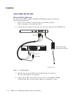
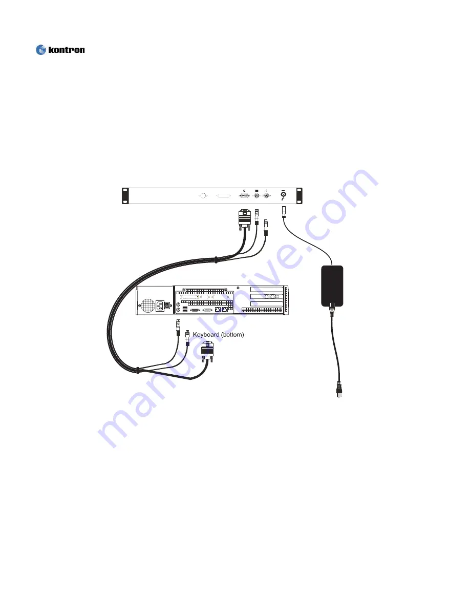
RMVS-1U.XXXX No KVM Setup

To connect the no KVM version of the RMVS-1U.XXXX keyboard/monitor drawer,
perform the following steps:

1) Turn off your computer. You should always turn off the computer

before connecting or disconnecting a device.

2) Connect the video cable to the video ports on both your computer and the RMVS unit.

Figure 1-3. Cabling Diagram

3) Identify and connect the PS/2 mouse and PS/2 keyboard connector to

the correct PS/2 ports on the computer.

4) Connect the 12 VDC power cable to the power inlet on the RMVS-1U.XXXX

LCD/keyboard drawer and the power adapter to an suitable AC source.

Mouse (top)

Video (VGA)

To power source

S Video

DVI

VGA

Mouse

Keyboard

Video (VGA)

DC12V 5A output
Desktop Transformer

DC12V

+

RMVS-1U LCD/Keyboard Drawer Series User’s Guide

Summary of Contents for RMVS-1U

Page 1: ...RMVS 1U LCD Keyboard Drawer Series User s Guide November 2003 6260 Sequence Drive San Diego CA 92121 4371 800 523 2320 fax 858 677 0895 www kontron com...

Page 2: ...ability arising out of the application or use of the information or products described herein This document may contain or reference information and products protected by copyrights or patents and doe...

Page 3: ...icherheitsanweisungen Installationsvorkehrungen xxi Gestell Einbau Vorsichtsmassnahmen xxii Wartungs und Reparaturvorsichtsma nahmen xxiii Regulatory Compliance Statements FCC Compliance Statement for...

Page 4: ...Installation Problems 3 2 Additional Screen Displays 3 4 Video Cable Not Connected 3 4 Video Signal Out of Specification 3 4 Power Saver 3 5 Video Connector Pin Assignment 3 6 Chapter 4 Specification...

Page 5: ...uto Adjustment 2 3 Figure 2 3 Brightness 2 4 Figure 2 4 15 17 On Screen Display OSD 2 4 Tables Table 1 1 Video Timing and Display Resolution Specifications 1 2 Table 2 1 Monitor Adjustment Controls 15...

Page 6: ...This page intentionally left blank Vi RMVS 1U LCD Keyboard Drawer Series User s Guide...

Page 7: ...ion programs and save files Note Additional technical information is available from the Kontron Web site www Kontron com Customer Comments If you experience any problems with this manual or just want...

Page 8: ...This page intentionally left blank Viii RMVS 1U LCD Keyboard Drawer Series User s Guide...

Page 9: ...to a minimum 20 restocking charge and charges for any damaged or missing parts Products not returned within 60 days of purchase or products which are not in an as new and resaleable condition are not...

Page 10: ...s for Warranty must include a Failure Report for each unit by serial number s as well as a copy of the original invoice showing the date of purchase To reduce risk of damage returns of product must be...

Page 11: ...der Kontron s liability shall in no event exceed the purchase price of the product purchased hereunder The foregoing limitation of liability shall be equally applicable to any service provided by Kont...

Page 12: ...This page intentionally left blank xii RMVS 1U LCD Keyboard Drawer Series User s Guide...

Page 13: ...type of advisory Use caution when servicing any electrical component Note A Note indicates information that will help you make better use of the system Disclaimer We have tried to identify all situat...

Page 14: ...This page intentionally left blank xiv RMVS 1U LCD Keyboard Drawer Series User s Guide...

Page 15: ...o rain or moisture Installation Precautions In addition take note of these installation precautions when appropriate When you disconnect the power cable from the socket pull on the plug not the cord T...

Page 16: ...he display contains glass parts Dropping the drawer may cause the glass parts to break To help protect the drawer from sudden transient increases and decreases in electrical power use a surge suppress...

Page 17: ...outlet and refer servicing to qualified service personnel in the event that Liquid is spilled in to the product or the product is exposed to rain or water The product does not operate properly when t...

Page 18: ...This page intentionally left blank xviii RMVS 1U LCD Keyboard Drawer Series User s Guide...

Page 19: ...urchf hren Hinweis Ein Hinweis enth lt Informationen die es erleichtern das Ger t in Gebrauch zu nehmen Haftungsausschlu Es wurde versucht alle Situationen die eine Warnung oder einen Vorsichtshinweis...

Page 20: ...This page intentionally left blank xx RMVS 1U LCD Keyboard Drawer Series User s Guide...

Page 21: ...ehrungen Das Netzkabel immer am Stecker nicht am Kabel herausziehen Um einen Schlag zu vermeiden mu das Netzkabel immer mit einem geerdeten und ordnungsgem verdrahteten Netzanschlu verbunden sein Kein...

Page 22: ...rspannung auf den berspannungsschutz und die Versorgungsleitungen m ssen beachtet werden Beachten Sie die Leistungsschild Nennwerte Die Umgebungstemperatur innerhalb des Gestells kann h her als die Um...

Page 23: ...n Fl ssigkeit in das Ger t versch ttet wurde oder es mit Regen oder Wasser in Kontakt kam das Ger t nicht ordnungsgem betrieben werden kann nachdem alle Anweisungen befolgt wurden das Ger t fallen gel...

Page 24: ...xxiv This page intentionally left blank RMVS 1U LCD Keyboard Drawer Series User s Guide...

Page 25: ...not occur in a particular installation If this equipment does cause harmful interference to radio or television reception which can be determined by turning the equipment off and on the user is encour...

Page 26: ...or television reception which can be determined by turning the equipment off and on the user is encouraged to try to correct the interference by one or more of the following measures Reorient or reloc...

Page 27: ...anadian Interference Causing Equipment Regulations CE Marking The product s described in this manual complies with all applicable European Union CE directives RMVS 1U LCD Keyboard Drawer Series User s...

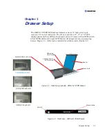
Page 28: ...1 2 Front View RMVS 1U XXXX Drawer Keyboard Mouse options Monitor OnScreen display OSD controls Momentary On off switch Key Lock Drawer Handle display panel and three different keyboard options It com...

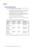
Page 29: ...witch options Your Macintosh will require a mac adapter for video Your video card must be capable of operating in the ranges indicated in Table 1 1 Table 1 1 Video Timing and Display Resolution Specif...

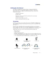
Page 30: ...g cables and accessories 2 Keys for key lock 1 AC Power cable 2 Keys for key lock 1 AC Power cable 8 Rack ear and rear bracket mounting hardware 1 Desktop Transformer with no KVM have headers at the b...

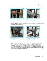
Page 31: ...Kontron technical support To install the RMVS 1U XXXX with slide rails into a rack follow these steps 1 Determine the mounting location and mark the rack mounting holes in front and at the rear of the...

Page 32: ...driver and the 4 remaining 10 32 screws Secure the RMVS 1U XXXX to the rack frame Figure 6 Remove the 10 32 screws you were using as stops and install them into the remaining 4 hold of the rack ears...

Page 33: ...ear bracket hardware Figure 7 from procedure 2 The RMVS 1U XXXX is now mounted in the rack Figure 8 To use the unit unlock the unit grasp the handle and pull it out to the fully extended and locked po...

Page 34: ...ed by the manufacturer of the video card Most video cards use the Windows Display Properties control panel to configure the display To open the Windows Display Properties click the right mouse button...

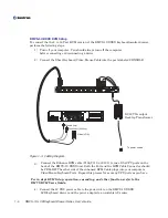
Page 35: ...e video ports on both your computer and the RMVS unit Figure 1 3 Cabling Diagram 3 Identify and connect the PS 2 mouse and PS 2 keyboard connector to the correct PS 2 ports on the computer 4 Connect t...

Page 36: ...AIN IN CHAIN OUT N A For St No 1 1 2 CPU 3 4 5 6 7 8 9 10 11 12 13 14 15 16 KVM 3 Connect the Enhance KVM cable C106 C110 or C120 to one of the CPU ports on the back of the RMVS 1U XXXX unit Both the...

Page 37: ...1 10 RMVS 1U LCD Keyboard Drawer Series User s Guide This page intentionally left blank...

Page 38: ...1 11 RMVS 1U LCD Keyboard Drawer Series User s Guide This page intentionally left blank...

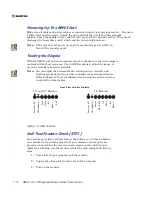
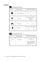
Page 39: ...n menu to adjust the video display Figure 1 5 OSD Controls Self Test Feature Check STFC Your monitor provides a self test feature that allows you to check whether your monitor is functioning properly...

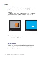
Page 40: ...at least 20 minutes before making any screen adjustments 15 and 17 Monitors If you have a 15 or 17 monitor and it is functioning properly you will see two orange boxes with the text inside the second...

Page 41: ...its will require at least 30 minutes to warm up stabilize completely and reach their optimal operating point Some image characteristics such as image centering and black level will vary until the unit...

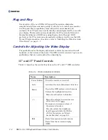
Page 42: ...e display adjustment controls are located on the left hand side at the bottom of the bezel The OSD controls consist of up to seven pushbuttons that are used to adjust the video display Table 2 1 Monit...

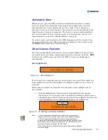
Page 43: ...pear automatically Auto Adjustment Figure 2 1 Auto Adjustment Even though your computer system can recognize your new LCD monitor the auto adjustment function will optimize the display settings for us...

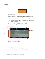
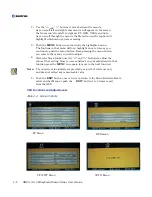
Page 44: ...rightness push the button to decrease the brightness On Screen Display OSD 15 and 17 Figure 2 4 On Screen Display OSD Accessing the Menu System To access the menu system follow these steps 1 With the...

Page 45: ...other menu s will appear on the screen the four menu s from left to right are PC OSD Utility and Auto As you scroll through the menu s the Menu Icon on the top bar will highlight which menu you are a...

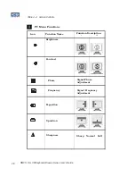
Page 46: ...Signal Phase Adjustment Signal Frequency Adjustment Icon Function Description Function Name Brightness Contrast PC Menu Functions Sharpness Sharp Normal Soft 2 6 RMVS 1U LCD Keyboard Drawer Series Us...

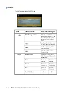
Page 47: ...hite Sets the color to a cool bluish white Color Control Adjusts the saturation of Red Green and Blue in the display area R ed Decreases Redness Increases Redness G reen Decreases Greenness Increases...

Page 48: ...Description Function Name OSD H position OSD V position 5 to 200 Seconds 5 Second Intervals Decrease Time Increase Time OSD Language Language sets the OSD to display in one of six languages The langua...

Page 49: ...l and Vertical Frequency Resolution Factory Reset No Yes Half Tone Half Tone Color on OSD Off On Reset Menu Functions Icon Function Description Function Name Auto Auto Setting Press MENU Key Used to A...

Page 50: ...the video signal character istics due to the video graphics adapter and it narrows the range of user adjustable parameter When your LCD monitor detects this video signal and reaches the limit it displ...

Page 51: ...utton the monitor automatically saves any adjustments you have made These changes are saved into a user area in the monitor User areas are reserved according to the signal frequency from your computer...

Page 52: ...ecrease the brightness Contrast Figure 2 7 Contrast Follow these instructions to adjust the Contrast of the monitor s display 1 With the menu off push the or UP ARROW button to display the Contrast sc...

Page 53: ...numeric value indicator is provided as a point of reference only and does not reflect any measureable value 5 After scrolling through the sub menus and selecting a function use the and buttons to adj...

Page 54: ...D Level 1 Level 2 Level 3 Level 4 Phase Frequency Signal Phase Adjustment Signal Frequency Adjustment Icon Function Description Function Name Brightness Contrast Table 2 4 Display Control for 19 Color...

Page 55: ...rol Continued H position V position Icon Function Description Function Name Position Size Control Fill Screen Expands video to fit screen Fill to Aspect Ratio Shows video true aspect ratio Zoom After...

Page 56: ...U to reset the display to the original factory settings OSD H position Position OSD V position Position OSD Background Mode Highlight and press MENU to access the OSD Background Mode menu Use the Up D...

Page 57: ...ideo adapter you are using the lower limit of the control can not go down to Min Number on OSD or go up to Max Number on OSD This is due to the video signal character istics due to the video graphics...

Page 58: ...aintaining Your RMVS 1U XXXX Keyboard Monitor Drawer To maintain your drawer and keep the unit operating at peak performance Keep your display screen clean Adjust the OSD controls Refer to Chapter 2 f...

Page 59: ...pins are bent in the video cable connector Check that the video card is firmly seated in the card slot in your computer Is the unit in Power Management mode Touch the screen if applicable press any k...

Page 60: ...the Fine function Image is not atable and may appear to vibrate Check that the display resolution and frequency from your PC or video board is an available mode for your monitor On your computer chec...

Page 61: ...computer this information is not displayed Video Signal Out of Specification If the video sync signals do not meet the monitor specifications the unit will display the following screen The message wi...

Page 62: ...XXXX keyboard monitor drawer Table 3 1 Power Saving Modes Note This monitor automatically returns to normal operation when horizontal and vertical sync return This occurs when you move the computer s...

Page 63: ...Video Input Pin Assignment 15 pin D sub connector Pin Separate H V Composite H V Sync on green 1 Red Red Red 2 Green Green Green 3 Blue Blue Blue 4 GND GND GND 5 GND DDC Return GND DDC Return GND DDC...

Page 64: ...vel DDC1 2B On screen Adjustment Contrast brightness H position V position phase clock factory defaults auto setup colo r and language MTBF 25 000hrs Chassis Drawer Mounting Standard 19 inch rack Slid...

Page 65: ...f on key engraving options available by special order Integrated Pointing Device High quality 16mm trackball Cirque glidepad allows full mouse Sealed pressure pointer and 2 button mouse functionality...

Page 66: ...nformity with Part 15B Class B CE Conformity with EU EMC Directive 89 336 EEC EU Low Voltage Directive 72 23 EEC UL cUL Listed to UL cUL 60950 Third Edition TUV GS Mark Certification RMVS 1U 15XX and...

Page 67: ...des Frequency KHz Polarity Frequency Hz Polarity 1 720x400 900x449 31 47 N 70 0 P 28 322 2 640x480 800x525 31 47 N 60 0 N 25 175 3 640x480 864x525 35 00 N 66 7 N 30 240 4 640x480 832x520 37 86 N 72 8...

Page 68: ...1040x666 48 08 P 72 2 P 50 000 10 800x600 1056x625 46 87 P 75 0 P 49 500 11 800x600 1048x631 56 67 P 85 1 P 56 250 12 832x624 1152x667 49 73 N 74 6 N 57 284 13 1024x768 1344x806 48 36 N 60 0 N 65 000...

Page 69: ...factory presets e VESA Standard Mode 1 Pixel freq Resolution 640 x 350 Industry Standard VESA Standard IBM VGA 3H 720 x 400 640 x 480 640 x 480 VESA Standard VESA Guidelines 640 x 480 800 x 600 VESA...

Page 70: ...of the Glide Pad Technology integrated into your RMVS 1U XXBX Drawer This technology is easy to use once acquainted with We have provided a simple tutorial to acquaint you with the functions of the G...

Page 71: ...chnical documentation required to demonstrate this product meets the requirements of the EMC Directive and the Low Voltage Directive has been compiled by Kontron and is available for inspection by the...

Reviews: