KBox A-103 – User Guide, Rev. 3.0
// 21
The device is designed to be operated in:
Vertical position: (KBox A-103 configuration with vertical mounting plate) mounted inside a control cabinet or
Vertical/horizontal: wall mounted (KBox A-103 configuration with wall mounting brackets) or
Horizontal position: KBox A-103 as desktop unit (equipped with the supplied rubber feet) or
Vertical/horizontal: KBox A-103 DIN Rail mounting (with DIN Rail mounting clip)
When powering on the KBox A-103, make sure that the cooling fins of the chassis (Figure 15,
Figure 16 and Figure 17, pos. 6) are not obstructed (covered) by any objects.
To provide sufficient heat dissipation by the cooling of the device, do not cover the cooling
fins of the
KBox A-103. Do not place any objects on the device. When installing the system, please note
the clearance recommendation in the section 7.1 “System Mounting”.
Please observe that the expansion of your system with an mPCIe WLAN card (and the
corresponding antennas) and/or GPIO port, allows you to use the KBox A-103 only as
desktop unit or equipped with brackets for vertical/horizontal wall/table mounting.
The KBox A-103 equipped with an mPCIe WLAN card with the corresponding antennas
and/or GPIO port is not possible to operate vertical mounting in a control cabinet.
4.1.
RTC
The KBox A-103 comprises a chipset external RTC. This RTC is connected to the SMBus of the processor module. A RTC
of type RV-8564 or compatible is used. To provide a valid date and time when no power is connected to the KBox A-
103, the RTC is equipped with a goldcap buffer.
4.1.1.
RTC Buffer Time
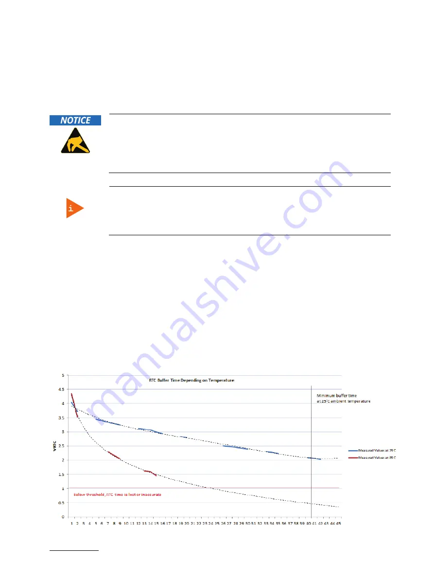
The RTC buffer time is depending of the ambient temperature.
If the time is not valid this is indicated by a status bit in the RTC registers. For details see the RV-8564 application
manual.
Figure 2: RTC buffer time diagram


