CP6006-SA – User Guide, Rev. 0.5 Preliminary
// 53
3.3.2.
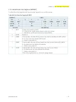
Reset Status Register (RSTAT)
The Reset Status Register is used to determine the host’s reset source.
Table 33: Reset Status Register (RSTAT)
ADDRESS
0x285
BIT
7
6
5
4
3
2
1
0
NAME
PORS
Reserved
SRST
Reserved
IPRS
FPRS
CPRS
WTRS
ACCESS
R/W
R
R/W
R
R/W
R/W
R/W
R/W
RESET
N/A
0
0
0
0
0
0
0
BITFIELD
DESCRIPTION
7
PORS
Power-on reset status:
0 = System reset generated by warm reset
1 = System reset generated by power-on (cold) reset
Writing a ’1’ to this bit clears the bit.
5
SRST
Software reset status:
0 = Reset is logged by the IPMI controller
1 = Reset is not logged by IPMI controller
The uEFI BIOS
/
software sets this bit to inform the IPMI controller that the next reset
should not be logged.
3
IPRS
IPMI controller reset status:
0 = System reset not generated by IPMI
1 = System reset generated by IPMI
Writing a ’1’ to this bit clears the bit.
2
FPRS
Front panel push button reset status:
0 = System reset not generated by front panel reset
1 = System reset generated by front panel reset
Writing a ’1’ to this bit clears the bit.
1
CPRS
CompactPCI reset status (PRST signal):
0 = System reset not generated by CompactPCI reset input
1 = System reset generated by CompactPCI reset input
Writing a ’1’ to this bit clears the bit.
0
WTRS
Watchdog timer reset status:
0 = System reset generated by Watchdog timer
1 = System reset generated by Watchdog timer
Writing a ’1’ to this bit clears the bit.
The Reset Status Register is set to default values by power-on (cold) reset, not by a warm
reset.


