background image

CP-RIO6-001/-DD-216/-HD/-HD-216

Introduction

ID 1043-5620, Rev. 2.0

Page 1 - 11

General

Temperature Range

Operational:

0°C to +60°C

Standard

-40°C to +85°C

E2 (optional)

Storage: -55°C to +85°C

Without any additional components 

Mechanical

6U, 4HP, CompactPCI-compliant form factor

Dimensions

233.35 mm x 80 mm

Board Weight

CP-RIO6-001:

224 g (without USB NAND Flash module)

CP-RIO6-001-DD-216: 224 g (without USB NAND Flash module)
CP-RIO6-001-HD:

218 g (without USB NAND Flash module)

CP-RIO6-001-HD-216: 218 g (without USB NAND Flash module)

Table 1-2: CP-RIO6-001/-DD-216/-HD/-HD-216 Main Specifications (Continued)

CP-RIO6-001/-DD-216/

-HD/-HD-216

SPECIFICATIONS

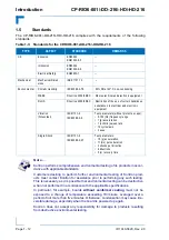
Note ...

When additional components are installed, refer
to their operational specifications as this will influ-
ence the modules’ operational and storage tem-
perature.

Summary of Contents for CP-RIO6-001

Page 1: ...If it s embedded it s Kontron User Guide CP RIO6 001 CP RIO6 001 DD 216 CP RIO6 001 HD CP RIO6 001 HD 216 6U CompactPCI Rear Transition Modules Doc ID 1043 5620 Rev 2 0 August 17 2012...

Page 2: ...s for information purposes only and not guaranteed for legal purposes Information has been carefully checked and is believed to be accurate however no responsibility is assumed for inaccuracies Kontro...

Page 3: ...Instructions xi General Instructions on Usage xii Two Year Warranty xiii 1 Introduction 1 3 1 1 Board Overview 1 3 1 2 CP RIO6 001 DD 216 HD HD 216 Feature Comparison 1 4 1 3 Board Diagrams 1 4 1 3 1...

Page 4: ...s 2 10 2 1 7 Rear I O interface on Compact PCI Connectors rJ3 rJ4 and rJ5 2 11 3 Installation 3 3 3 1 Safety Requirements 3 3 3 2 Rear I O Module Installation Procedures 3 4 3 3 Rear I O Module Remova...

Page 5: ...or J17 Pinout 2 7 2 6 SATA Connector J19 Pinout 2 8 2 6 Serial Port Connector J15 RS 232 RS 422 Pinout 2 9 2 7 Serial Port Connector J16 RS 232 Pinout 2 9 2 8 Fan Control Con J12 and J13 Pinout 2 10 2...

Page 6: ...Preface CP RIO6 001 DD 216 HD HD 216 Page vi ID 1043 5620 Rev 2 0 This page has been intentionally left blank...

Page 7: ...O6 001 DD 216 Board Layout Front View 1 8 1 5 CP RIO6 001 HD CP RIO6 001 HD 216 Board Layout Front View 1 9 2 1 USB Con J6 and J7 2 3 2 2 USB NAND Flash Con J18 2 4 2 3 DVI Connectors J9 J11 2 5 2 4 D...

Page 8: ...Preface CP RIO6 001 DD 216 HD HD 216 Page viii ID 1043 5620 Rev 2 0 This page has been intentionally left blank...

Page 9: ...ron reserves the right to change modify or improve this document or the product described herein as seen fit by Kontron without further notice Trademarks Kontron the PEP logo and if occurring in this...

Page 10: ...Sensitive Device This symbol and title inform that electronic boards and their compo nents are sensitive to static electricity Therefore care must be taken during all handling operations and inspectio...

Page 11: ...ls This is most easily done by touching a metal part of your system housing It is particularly important to observe standard anti static precautions when changing piggy backs ROM devices jumper settin...

Page 12: ...c environmental requirements This applies also to the operational temperature range of the specific board version which must not be exceeded If batteries are present their temperature restrictions mus...

Page 13: ...efund the original cost of purchase if appropriate In the event of repair re funding or replacement of any part the ownership of the removed or replaced parts reverts to Kontron and the remaining part...

Page 14: ...Preface CP RIO6 001 DD 216 HD HD 216 Page xiv ID 1043 5620 Rev 2 0 This page has been intentionally left blank...

Page 15: ...CP RIO6 001 DD 216 HD HD 216 Introduction ID 1043 5620 Rev 2 0 Page 1 1 Introduction Chapter 1 1...

Page 16: ...Introduction CP RIO6 001 DD 216 HD HD 216 Page 1 2 ID 1043 5620 Rev 2 0 This page has been intentionally left blank...

Page 17: ...port two onboard COM ports and two onboard fan connectors The CP RIO6 001 DD 216 comes with three USB 2 0 ports two digital video ports one on board SATA port two onboard COM ports and two onboard fa...

Page 18: ...dummy plugs are fitted to these connectors as protective caps to prevent their unintentional use 1 3 Board Diagrams The following diagrams provide additional information concerning the boards functio...

Page 19: ...l Block Diagram xxx xxx Onboard Connector Front Panel Connector CPCI Connectors rJ3 rJ4 rJ5 SATA Connector 7 pin HDMI DVI SATA xxx Controller Driver HDMI DVI DVI Connector DVI Connector RS 232 2x GbE...

Page 20: ...ram xxx xxx Onboard Connector Front Panel Connector CPCI Connectors rJ3 rJ4 rJ5 SATA Connector 7 pin SATA xxx Controller Driver HDMI DVI DVI Connector RS 232 SATA Socket SATA 2x GbE 2x Mag 2x Ethernet...

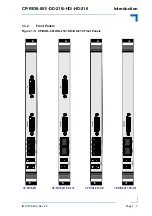
Page 21: ...IO6 001 DD 216 HD HD 216 Introduction ID 1043 5620 Rev 2 0 Page 1 7 1 3 2 Front Panels Figure 1 3 CP RIO6 001 DD 216 HD HD 216 Front Panels CP RIO6 001 DD 216 CP RIO6 001 HD 216 CP RIO6 001 HD CP RIO6...

Page 22: ...d Layout Figure 1 4 CP RIO6 001 CP RIO6 001 DD 216 Board Layout Front View rJ3 rJ5 rJ4 USB USB Magn Magn J6 J7 GbE B GbE A J8 J16 COM A J15 COM B J17 SATA HDMI DVI J11 HDMI DVI J9 Protective Caps CP R...

Page 23: ...9 Figure 1 5 CP RIO6 001 HD CP RIO6 001 HD 216 Board Layout Front View DVI HDMI J9 CP RIO6 001 HD 216 only J18 USB NAND Flash 1 2 10 9 1 2 10 9 1 2 10 9 1 1 J12 J13 1 7 S1 J19 SATA HDD rJ3 rJ5 rJ4 US...

Page 24: ...8A B CP RIO6 001 DD 216 CP RIO6 001 HD 216 Ethernet not supported due to the fact that the Ethernet interface is isolated on the CompactPCI connector rJ3 USB Two USB 2 0 interfaces on type A connector...

Page 25: ...ard Weight CP RIO6 001 224 g without USB NAND Flash module CP RIO6 001 DD 216 224 g without USB NAND Flash module CP RIO6 001 HD 218 g without USB NAND Flash module CP RIO6 001 HD 216 218 g without US...

Page 26: ...min sweep rate 10 cycles axis 3 axes Single Shock IEC61131 2 IEC60068 2 27 Test parameters 15 g acceleration 11 ms pulse duration 3 shocks per direction 6 directions 5 s recovery time Note Kontron per...

Page 27: ...001 DD 216 HD HD 216 Table 1 4 Related Publications PRODUCT PUBLICATION CompactPCI Systems and Boards CompactPCI Specification 2 0 Rev 3 0 CompactPCI Packet Switching Backplane Specification PICMG 2...

Page 28: ...Introduction CP RIO6 001 DD 216 HD HD 216 Page 1 14 ID 1043 5620 Rev 2 0 This page has been intentionally left blank...

Page 29: ...CP RIO6 001 DD 216 HD HD 216 Functional Description ID 1043 5620 Rev 2 0 Page 2 1 Functional Description Chapter 1 2...

Page 30: ...Functional Description CP RIO6 001 DD 216 HD HD 216 Page 2 2 ID 1043 5620 Rev 2 0 This page has been intentionally left blank...

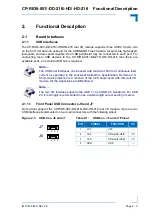
Page 31: ...n the front panel of the CP RIO6 001 DD 216 HD HD 216 rear I O module there are two USB interfaces implemented on two 4 pin connectors with the following pinout Note The USB host interfaces can be use...

Page 32: ...rd disk emulation and a high data transfer rate It is optimized for embedded systems providing high performance reliability and security Note Only qualified USB 2 0 NAND Flash modules from Kontron are...

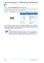
Page 33: ...connecting a digital monitor Figure 2 3 DVI Connectors J9 J11 The following table indicates the pinout of the DVI Connectors J9 J11 Table 2 3 DVI Connectors J9 J11 Pinouts PIN SIGNAL DESCRIPTION I O P...

Page 34: ...lit it means that a link has been established The LED blinks when network packets are sent or received through the RJ 45 port When this LED is not lit there is no link established LINK green This LED...

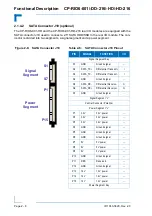
Page 35: ...RIO6 001 DD 216 HD HD 216 rear I O module is equipped with a SATA connector J17 used to connect a standard SATA device to the rear I O module via a SATA cable The rear I O module will not exceed the t...

Page 36: ...FUNCTION I O Signal Segment Key S1 GND Ground signal S2 SATA_TX Differential Transmit I S3 SATA_TX Differential Transmit I S4 GND Ground signal S5 SATA_RX Differential Receive O S6 SATA_RX Differenti...

Page 37: ...ESCRIPTION I O I Data carrier detect DCD 1 RX Receive data I I Data send request DSR 2 RX Receive data I I Receive data RXD 3 NC Not connected O Request to send RTS 4 NC Not connected O Transmit data...

Page 38: ...board fan connectors J12 and J13 for connecting two external cooling fans Note The maximum allowable continuous load current on each fan interface is 300 mA Figure 2 8 Fan Control Con J12 and J13 J12...

Page 39: ...rJ5 Figure 2 9 Rear I O CompactPCI Connectors rJ3 rJ4 and rJ5 Note To support the rear I O feature a 6U CompactPCI backplane with rear I O sup port as well as a compatible and correctly configured CPU...

Page 40: ...0 D GND USB2 D USB2 D GND 7 NC RIO_3 3V NC ID3 ID4 SPEAKER GND 6 NC RSV RSV RSV RSV RSV GND 5 NC RSV RSV RSV RSV RSV GND 4 NC SP1 RI SP1 NC SP1 DTR SP1 NC SP1 CTS SP1 TX SP1 TX SP1 TX RSV GND 3 NC SP1...

Page 41: ...NC RSV RSV RSV RSV RSV GND 5 NC RSV RSV RSV RSV RSV GND 4 NC SP1 RI SP1 NC SP1 DTR SP1 NC SP1 CTS SP1 TX SP1 TX SP1 TX RSV GND 3 NC SP1 RTS SP1 NC SP1 RX SP1 NC SP1 DSR SP1 RX SP1 DCD SP1 RX RSV GND 2...

Page 42: ...RSV RSV GND RSV RSV GND 12 14 Key Area 11 NC RSV RSV GND RSV RSV GND 10 NC RSV RSV GND RSV RSV GND 9 NC GND GND GND GND GND GND 8 NC RSV RSV GND RSV RSV GND 7 NC RSV RSV GND RSV RSV GND 6 NC GND GND...

Page 43: ...SDC GND 14 NC GND GND GND GND GND GND 13 NC DVI1 D0 DVI1 D0 GND DVI1 D1 DVI1 D1 GND 12 NC DVI1 D2 DVI1 D2 GND RSV RSV GND 11 NC RSV DVI1 HPDET GND DVI1 SDA DVI1 SDC GND 10 NC DVI1 CLK DVI1 CLK GND RSV...

Page 44: ...Functional Description CP RIO6 001 DD 216 HD HD 216 Page 2 16 ID 1043 5620 Rev 2 0 This page has been intentionally left blank...

Page 45: ...CP RIO6 001 DD 216 HD HD 216 Installation ID 1043 5620 Rev 2 0 Page 3 1 Installation Chapter 1 3...

Page 46: ...Installation CP RIO6 001 DD 216 HD HD 216 Page 3 2 ID 1043 5620 Rev 2 0 This page has been intentionally left blank...

Page 47: ...that the system main power is removed prior to installing or removing the CP RIO6 001 DD 216 HD HD 216 Ensure that there are no other external voltages or signals being applied to the CP RIO6 001 DD...

Page 48: ...9 Ensure that the rear I O module and all required interfacing cables are properly secured The rear I O module is now ready for operation Warning Failure to comply with the instruction below may caus...

Page 49: ...de information re garding installation aspects and not detailed procedures 3 4 1 USB Device Installation The CP RIO6 001 DD 216 HD HD 216 supports all USB Plug and Play computer peripherals e g keyboa...

Page 50: ...stallation of an External Serial ATA Device One external SATA device may be connected to the CP RIO6 001 DD 216 HD HD 216 via the onboard SATA connector J17 as well as the appropriate SATA cable Some...

Page 51: ...rd SATA connector and properly secured via the four mounting screws The following figure shows the placement of the 2 5 SATA HDD SSD on the CP RIO6 001 HD HD 216 Figure 3 1 Placement of the 2 5 SATA H...

Page 52: ...Installation CP RIO6 001 DD 216 HD HD 216 Page 3 8 ID 1043 5620 Rev 2 0 This page has been intentionally left blank...

Reviews: