Functional Description
CP-RIO6-001/-DD-216/-HD/-HD-216
Page 2 - 12
ID 1043-5620, Rev. 2.0
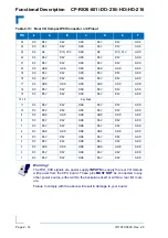
The following table describes the signals of the rJ3 connector used on the CP-RIO6-001/-HD.
Table 2-9: CP-RIO6-001/-HD Rear I/O CompactPCI Connector rJ3 Pinout
PIN
Z
A
B
C
D
E
F
19
NC
RIO_VCC
RIO_VCC
RIO_3.3V
RIO_+12V
RIO_-12V
GND
18
NC
LPa_DA-
GND
LPa_DC-
GND
17
NC
LPa_DB-
GND
LPa_DD-
GND
16
NC
LPb_DA-
GND
LPb_DC-
GND
15
NC
LPb_DB-
GND
LPb_DD-
GND
14
NC
LPa:LINK
LPb:LINK
LPab:CT1
LPc:LINK
FAN:SENSE2 GND
13
NC
LPa:ACT
LPb:ACT
NC
NC
FAN:SENSE1
GND
12
NC
NC
NC
GND
NC
NC
GND
11
NC
NC
NC
GND
NC
NC
GND
10
NC
USB1:VCC
USB0:VCC
GND
RSV
USB2:VCC
GND
9
NC
USB1:D-
USB1:D+
GND
RSV
RSV
GND
8
NC
USB0:D-
USB0:D+
GND
USB2:D-
USB2:D+
GND
7
NC
RIO_3.3V
NC
ID3
ID4
SPEAKER
GND
6
NC
RSV
RSV
RSV
RSV
RSV
GND
5
NC
RSV
RSV
RSV
RSV
RSV
GND
4
NC
SP1:RI
SP1:NC
SP1:DTR
SP1:NC
SP1:CTS
SP1:TX-
SP1:TX
SP1:TX+
RSV
GND
3
NC
SP1:RTS
SP1:NC
SP1:RX
SP1:NC
SP1:DSR
SP1:RX-
SP1:DCD
SP1:RX+
RSV
GND
2
NC
SP0:RI
SP0:DTR
SP0:CTS
SP0:TX
RSV
GND
1
NC
SP0:RTS
SP0:RX
SP0:DSR
SP0:DCD
ID1
GND
Warning!
The RIO_XXX signals are power supply
INPUTS
to supply the rear I/O module
with power from the CPU board. These pins
MUST NOT
be connected to any
other power source, either within the backplane itself or within a rear I/O module.
Failure to comply with the above will result in damage to your board.
Table 2-10: CP-RIO6-001/-HD Rear I/O CompactPCI Connector rJ3 Signals
SIGNAL
DESCRIPTION
SP0
COMA Signaling RS-232
SP1
COMB Signaling RS-232/RS-422
USB0 to USB2
USB Port Signaling
SPEAKER
Standard PC Speaker
FAN
Fan Sensoring
LPa
Rear I/O LAN Port B
LPb
Rear I/O LAN Port A

