413764/B
45
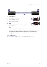
A
Bolt with suitable
diameter and length
B
Nut
C
Washer
D
Transducer cable
E
Blister bottom plate
F
Fill with suitable filling
compound (putty) to
reduce flow noise
Procedure
1
Lift the transducer up into is location, and align the holes on the transducer with the
holes in the blister or drop keel.
Observe the direction of the transducer. The "forward" marking must point towards
the bow of the vessel!
2
Insert the two bolts through the transducer and the blister or drop keel bottom plate.
3
Fasten the two nuts on the inside of the blister or drop keel.
Use Loctite 290 to secure the bolts.
4
Fill the two bolt holes in the transducer with a suitable filling compound (putty),
and smooth out the surface of the transducer face.
Any obstructions, cracks, dents or unevenness on the transducer face may cause
flow noise.
5
When the transducer has been fastened, inspect the plating around the transducer
face.
Important
Make sure that the surface of the transducer face, as well as the plating and putty
around the transducer is as even and smooth as possible. Obstructions on these
surfaces will create problems with turbulent flow, and may cause noise.
6
If required, allow the relevant maritime authority and/or classification society to
inspect and approve the transducer installation.
Summary of Contents for EA640
Page 62: ...62 413764 B 388697 WBT outline dimensions EA640 Installation Manual ...
Page 63: ...413764 B 63 Drawing file ...
Page 64: ...64 413764 B 400930 WBT Cabinet outline dimensions EA640 Installation Manual ...
Page 65: ...413764 B 65 Drawing file ...
Page 66: ...66 413764 B EA640 Installation Manual ...
Page 67: ...413764 B 67 Drawing file ...
Page 93: ......
Page 94: ... 2018 Kongsberg Maritime ...


