42
413764/B
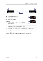
A
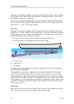
Service access (optional)
B
To transceiver
C
Steel conduit
D
Bushing, penetrates the hull plating
E
Washer
F
Rubber gasket
G
Packing nut
H
Cable service loop over the transducer
Context
The installation shipyard must provide all
necessary design and installation drawings,
as well as the relevant work standards
and mounting procedures. If required, all
documents provided by the shipyard for the
physical installation of the EA640 must be
approved by the vessel’s national registry
and corresponding maritime authority
and/or classification society. Such approval
must be obtained before the installation
can begin. The shipowner and shipyard
doing the installation are responsible for
obtaining and paying for such approval.
Important
Finalize the steel conduit installation before you pull the transducer cable through it.
Make sure that there are no spatter, sharp edges or protruding objects that can damage
the transducer cables. If a cable is damaged, and penetrated by water, the transducer
may be damaged beyond repair.
Procedure
1
Based on the vessel drawings, the physical properties of the decks and bulkheads,
and the physical locations of the WBT and the transducer, design the steel conduit.
The steel conduit must preferably be straight. Start the conduit immediately
above the transducer, and terminate it well above the water line. If you must
introduce bends on the steel conduit, take the minimum cable bending radius into
consideration.
2
Manufacture the steel conduit according to the relevant production standards.
3
Mount the steel conduit.
EA640 Installation Manual
Summary of Contents for EA640
Page 62: ...62 413764 B 388697 WBT outline dimensions EA640 Installation Manual ...
Page 63: ...413764 B 63 Drawing file ...
Page 64: ...64 413764 B 400930 WBT Cabinet outline dimensions EA640 Installation Manual ...
Page 65: ...413764 B 65 Drawing file ...
Page 66: ...66 413764 B EA640 Installation Manual ...
Page 67: ...413764 B 67 Drawing file ...
Page 93: ......
Page 94: ... 2018 Kongsberg Maritime ...

