background image

INSTRUMENTS AND CONTROLS

103

TWO-WHEEL STEERING “2WS” (travel)

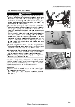
The two-wheel steering mode (2WS) allows the steering wheel to
control only the front wheels and must be used when travelling at
high speed and on public roads. The two-wheel steering mode
(2WS) allows all the available gears to be engaged.

NOTE

q

Every time the machine is started, the two-wheel steering mode
(2WS) is automatically selected, even if when it stopped the
selected mode was the four-wheel round (4WS ROUND) or the
four-wheel crab steering (4WS CRAB).

CAUTION

q

If the acoustic alarm sounds while the machine is
travelling, this means that the rear wheels are misaligned. 
The wheels can be realigned only if the speed is below 13
km/h and this operation is carried out by turning the
steering wheel, first to align the front wheels (LED 5 on)
and then to align the rear wheels (LED 6 on). 
The realignment operations should be carried out with the
machine at rest.

FOUR-WHEEL ROUND STEERING “4WS ROUND” 
(to be used in building sites when the machine must move in 
small spaces)

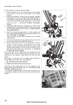
The four-wheel round steering mode allows the steering wheel to
control the front and rear wheels at the same time but in opposite
directions to perform tight curves in small areas or areas with
many obstacles.
The four-wheel round steering can be selected both with the
machine at rest and with the machine running, and changing over
from two-wheel steering to four-wheel round steering is possible
only if the 1st, 2nd or 3rd gear, manual or automatic, is engaged
and after the front wheels have been aligned (LED 5 on).

NOTE

q

The four-wheel round steering cannot be selected when the 4th
gear is engaged; the selection of the four-wheel round steering
with 4th gear engaged triggers the acoustic alarm to signal that
the manoeuvre is not correct, while changing over from two-
wheel steering to four-wheel steering will be possible only after
shifting down to the 3rd gear and after the speed has been
reduced below 13 km/h.

q

Changing over from four-wheel crab steering to four-wheel
round steering is possible only after the front wheels have been
realigned (LED 5 on).

q

Changing over from the four-wheel steering modes to two-
wheel steering is possible even while the machine is moving
and only after the rear wheels have been realigned (LED 6 on).

RKAB6360

RKAB6370

https://tractormanualz.com

Summary of Contents for Utility WB97S-5

Page 1: ...achine may cause serious injury or death Operators and maintenance personnel must read this manual before operating or maintaining this machine This manual should be kept inside the cab for reference and periodically reviewed by all personnel who will come into contact with the machine ATTENTION https tractormanualz com ...

Page 2: ...https tractormanualz com ...

Page 3: ...ons that have been carried out are important to have a clear prospect of the situation and to know exactly what has been done and what has to be done after the next maintenance interval Therefore it is advisable to consult both the hour meter and the maintenance plan frequently q Komatsu Dealers have gathered a considerable amount of experience over years of work in close contact with the users If...

Page 4: ...of this term must be limited to situations of extreme danger WARNING q Indicates a situation of potential danger that if not avoided may cause serious injury and even death CAUTION q Indicates a situation of potential danger that if not avoided may cause moderate injury This term can also be used as a warning in case of dangerous procedures Other terms used in the signs In addition to those indica...

Page 5: ... if this has been tampered with by modifying the standard setting of the hydraulic system WARNING q Before carrying out any electric welding operation disconnect the battery and the alternator See 2 8 13 PRECAUTIONS TO BE TAKEN WHEN HANDLING THE BATTERY AND THE ALTERNATOR WARNING q Install only authorized additional equipment See 6 1 AUTHORIZED OPTIONAL EQUIPMENT WARNING q The machine can travel o...

Page 6: ...ment is supplied by Komatsu these publications are enclosed to this manual q The instructions regarding the assembly of the authorized equipment the controls requiring special arrangements on the machine and the hydraulic couplings necessary for the operation of the equipment are grouped in the final section of this manual Komatsu BACKHOE LOADERS are constructed exclusively for the handling excava...

Page 7: ... load at the beginning of its service life its productivity and functionality will be untimely reduced Every new machine must be used carefully paying special attention to the following indications q After the start let the engine idle for 5 minutes in such a way as to warm it up gradually before actual operation q Avoid operating the machine with the limit loads allowed or at high speed q Avoid a...

Page 8: ...ised standards The Product Identification Number PIN is stamped on the lower part of the plate The customer must be able to indicate the PIN at any time that is why it must compulsorily be written in the following table The plate with the CE marking is applied inside the cab on the left vertical wall of the frame at the height of the brake pedals RKAB5970 RKAB2680 37A 98 11820 MODELLO MODEL TYP MO...

Page 9: ...UMERO DI OMOLOGAZIONE HOMOLOGATION NUMBER TIPO TYPE MODEL MASSA TOTALE AMMISSIBILE TOTAL MASS WEIGHT CARICO AMMISSIBILE ASSE ANT WEIGHT FRONT AXLE CARICO AMMISSIBILE ASSE POST WEIGHT REAR AXLE Product Identification Number PIN DA FROM DA FROM DA FROM A TO A TO A TO Massa rimorchiabile non atto POTENZA MOTORE MATRICOLA SERIAL NUMBER ANNO MANUFACTURED BY KOMATSU UTILITY EUROPE S p A 36025 NOVENTA VI...

Page 10: ...ine block bears the Manufacturer s mark and contains the following data 1 Engine type 2 Engine family 3 Serial number 4 EC Type Approval 5 EPA The serial number 3 is also stamped on the right side of the cylinder block on the upper part of the oil cooling heat exchanger 1 4 5 FRONT AXLE SERIAL NUMBER The serial number of the rear axle is stamped on the plate positioned on the right side of the axl...

Page 11: ...e of the axle body 1 4 7 TRANSMISSION SERIAL NUMBER The transmission serial number is stamped on the plate postioned on the right side of the transmission case 1 4 8 CAB SERIAL NUMBER The cab serial number is stamped on the plate postioned on the left side of the rear wall RKAB5990 RKAB2750 RKAB2740 https tractormanualz com ...

Page 12: ...ON 10 1 4 9 SERIAL NUMBERS AND DEALER S ADDRESS Machine no Mod Front axle no Rear axle no Transmission no Dealer Address Tel Contact person NOTES Cab no Product identification number PIN Engine no https tractormanualz com ...

Page 13: ...2 2 1 3 POSITION OF THE NOISE PLATES ON MACHINES WITH CAB 28 2 1 4 VIBRATIONS TO WHICH THE OPERATOR IS SUBJECTED 29 2 2 GENERAL PRECAUTIONS 30 2 2 1 GENERAL SAFETY RULES 30 2 2 2 SAFETY DEVICES AND GUARDS 30 2 2 3 CLOTHING AND PERSONAL PROTECTION ITEMS 30 2 2 4 UNAUTHORIZED MODIFICATIONS 31 2 2 5 LEAVING THE OPERATOR S SEAT 31 2 2 6 GETTING ON AND OFF THE MACHINE 32 2 2 7 CHECKING THE REAR VIEW MI...

Page 14: ...2 8 6 KEEPING THE MACHINE CLEAN 54 2 8 7 USE OF THE ENGINE DURING MAINTENANCE 54 2 8 8 PERIODICAL CHANGE OF THE SAFETY RELATED PARTS 54 2 8 9 STOP THE ENGINE BEFORE CARRYING OUT ANY MAINTENANCE OPERATION OR INSPECTION 55 2 8 10 RULES TO BE FOLLOWED DURING FUEL OR OIL TOPPING UP 56 2 8 11 CHECKING THE COOLANT LEVEL IN THE RADIATOR 56 2 8 12 USING LAMPS 56 2 8 13 P R E C A U T IO N ST OB ET A K E NW...

Page 15: ... 117 3 5 1 ENGINE HOOD 117 3 5 2 CAB 118 3 5 3 VENTILATION AND HEATING 121 3 5 4 AIR CONDITIONER if installed 122 3 5 5 SEAT 124 3 5 5 1 SEAT STANDARD 124 3 5 5 2 SEAT OPTIONAL 125 3 5 6 SAFETY BELT 126 3 5 7 FIRE EXTINGUISHER 126 3 5 8 FIRST AID KIT 126 3 5 9 TECHNICAL DOCUMENTATION 126 3 5 10 STORAGE COMPARTMENT 127 3 6 USE OF THE MACHINE 128 3 6 1 CHECKS TO BE CARRIED OUT BEFORE STARTING THE EN...

Page 16: ...DEWARDS 150 3 13 4 DIGGING METHOD 151 3 13 4 1 CHANGING THE BACKHOE BUCKET 152 3 14 LONG PERIODS OF INACTIVITY 153 3 14 1 PREPARING THE MACHINE FOR A LONG PERIOD OF INACTIVITY 153 3 14 2 PREPARING THE ENGINE FOR A LONG PERIOD OF INACTIVITY 154 3 14 3 MAINTENANCE DURING A PERIOD OF INACTIVITY 154 3 14 4 RESTARTING THE ENGINE 155 3 14 5 AFTER THE PERIOD OF INACTIVITY 155 3 15 TROUBLESHOOTING 156 3 1...

Page 17: ... FILTER only for machines with air conditioner 189 4 8 1 d CHECKING THE DETERGENT LEVEL IN THE WINDSHIELD WASHER RESERVOIR 189 4 8 1 e CHECKING THE WINDSHIELD WIPER BLADES 190 4 8 1 f LUBRICATING THE CAB DOOR HINGES 190 4 8 1 g FUSES AND RELAYS CHECK AND CHANGE 190 4 8 1 h BLEEDING THE BRAKING CIRCUIT 191 4 8 1 i CHECKING AND ADJUSTING THE WHEEL TOE IN 192 4 8 1 j CHECKING THE BRAKING EFFICIENCY 1...

Page 18: ... FUEL FILTER 215 4 8 10 e DRAINING THE FUEL TANK 216 4 8 10 f DRAINING THE HYDRAULIC OIL TANK only for machines in which synthetic biodegradable oil type HEES is used 217 4 8 10 g CLEANING THE OUTSIDE OF THE RADIATOR 218 4 8 10 h CLEANING THE OUTSIDE OF THE A C CONDENSER only for machines with air conditioner 219 4 8 11 MAINTENANCE EVERY 1000 HOURS OF OPERATION 220 4 8 11 a CHANGING THE FRONT AXLE...

Page 19: ...UIPMENT WITH UNIDIRECTIONAL OIL FLOW 243 6 3 4in1 BUCKET 244 6 3 1 DESCRIPTION AND CONTROLS 244 6 3 2 SAFETY DEVICES 244 6 3 3 INSTALLING THE 4in1 BUCKET 245 6 3 4 USING THE 4in1 BUCKET 246 6 3 5 MAINTENANCE 246 6 4 PALLET FORKS 247 6 4 1 DESCRIPTION 247 6 4 2 SAFETY DEVICES 248 6 4 3 USING THE FORKS 248 6 4 3 1 PREPARING THE PALLET FORKS FOR USE 249 6 4 3 2 OVERTURNING THE FORKS 249 6 4 4 REMOVIN...

Page 20: ...G THE CLAMSHELL BUCKET 268 6 9 3 USING THE CLAMSHELL BUCKET 269 6 9 4 MAINTENANCE 269 6 10 CONFIGURATION FOR THE USE OF THE HAND HYDRAULIC HAMMER 270 6 10 1 DESCRIPTION AND CONTROL 270 6 10 2 INSTALLING AND REMOVING THE HAND HAMMER 271 6 10 2 1 CONNECTING THE HAND HAMMER 271 6 10 2 2 REMOVING THE CONNECTIONS 272 6 10 3 USING THE HAMMER 272 6 10 4 MAINTENANCE 272 6 11 LOAD STABILIZER SYSTEM LSS Opt...

Page 21: ...SAFETY AND ACCIDENT PREVENTION 19 https tractormanualz com ...

Page 22: ...ANTE I TRASFERIMENTI SU STRADA I PEDALI FRENO DEVONO ESSERE COLLEGATI CON APPOSITO SPINOTTO 42N 93 11110 I NON INSERIRE LA DOPPIA TRAZIONE IN TRASFERIMENTO STRADALE GB D F E P DO NOT ENGAGE 4 WHEEL DRIVE DURING ROAD TRAVELLING W HREND DER STRASSENFAHRT NICHT DIE 4 RADANTRIEB EINSCHALTEN NE PAS ENGAGER LES 4x4 POUR LE DEPLACEMENT ROUTIER DESCONECTAR 4x4 ANTES DE CIRCULAR EN CARRETERA NˆO ENGRENE A ...

Page 23: ...SAFETY NOISE AND VIBRATION PLATES 21 SW L 1000 kg RKA16730 42N 93 11320 RKAB4740 42N 93 11310 https tractormanualz com ...

Page 24: ...following list WORK AREA q Do not approach or stand in the equipment operating radius when the boom and the bucket are lifted DO NOT OPEN THE ENGINE HOOD q Do not open or remove the hood when the engine is running HYDRAULIC OIL TOPPING UP q Only for machines in which synthetic biodegradable oil type HEES is used OVERTURNING THE FORKS q When overturning the forks for use or storage be very careful ...

Page 25: ...Do not bring the shock absorber near sparks or naked flames q Do not make holes in the shock absorber do not weld or use oxyhydrogen flames q Do not hit the shock absorber DO NOT START THE ENGINE WITH INCORRECT PROCEDURES q Start the engine and operate the machine only while seated with fastened safety belt q Do not attempt to start the engine by causing a short circuit with the terminals of the s...

Page 26: ...pposite pin DO NOT ENGAGE THE 4WD q When the machine travels on roads do not engage the 4WD HYDRAULIC OIL TOPPING UP HYDRAULIC OIL LEVEL PRIMA DI PARTIRE PER IL TRASFERIMENTO SU STRADA BLOCCARE LA LEVA COMANDO PALA 42N 93 12460 RKA14770 DURANTE I TRASFERIMENTI SU STRADA I PEDALI FRENO DEVONO ESSERE COLLEGATI CON APPOSITO SPINOTTO 42N 93 11110 RKA14780 I GB D F E P 42N 93 11120 RKA14790 37A 98 1221...

Page 27: ...ER REFUELLING FUEL FILTER ENGINE LUBRICATING OIL FILTER ENGINE AIR SUCTION FILTER ENGINE COOLANT 37A 98 12310 RKA14820 37A 98 12240 RKA14830 D 37A 98 12250 RKA14840 D 37A 98 12230 RKA14850 37A 98 12260 RKA14860 37A 98 12340 RKA14870 https tractormanualz com ...

Page 28: ...ESSURE TRANSMISSION OIL LEVEL TRANSMISSION OIL FILTER POWER OUTLET BOOM LOCK SWING LOCK 37A 98 12270 RKA14880 395 93 11440 RKA14590 395 93 11420 RKA14580 42N 93 11270 RKA14890 12 V 42N 93 11320 RKA14900 42N 93 11310 RKA14910 https tractormanualz com ...

Page 29: ... VIBRATION PLATES 27 ANCHORAGE POINT EMERGENCY EXIT BRAKE OIL DO NOT LIFT MORE THAN 1000 kg 42N 93 11360 RKA14920 42N 93 11260 RKA14930 B RAKE OI L B R A K E O I L RKA14940 RKA14950 SWL 1000 Kg https tractormanualz com ...

Page 30: ... for new ones to Komatsu or to your Komatsu Dealer q In case of replacement of a component provided with a noise plate make sure that this plate is applied also on the new piece NOISE OUTSIDE THE CAB q This value indicates the noise level outside the machine and refers to the noise perceived by persons in the vicinity of the work area NOISE INSIDE THE CAB q This value indicates the maximum noise l...

Page 31: ...ording to the results of the tests carried out to determine the vibrations transmitted to the operator by the machine the upper limbs are subjected to vibrations lower than 2 5 m sq sec while the seated part of the body is subjected to vibrations lower than 0 5 m sq sec https tractormanualz com ...

Page 32: ...nd always keep them in good operating conditions q Any improper use of the safety devices may result in serious injury or even death 2 2 3 CLOTHING AND PERSONAL PROTECTION ITEMS q Do not wear large or loose clothes rings and watches and do not approach the machine with loose long hair since they can get entagled in the moving parts of the machine and cause serious personal injury or damage Also av...

Page 33: ...tor s seat even if for a short time make sure that the machine is in a safe position See 2 4 12 PARKING THE MACHINE q Before leaving the operator s seat carry out the following operations in the sequence indicated below 1 Lower the equipment to the ground 2 Press the servo control locking button LED on 3 Apply the parking brake 4 Shift the reverse gear lever to the neutral position 5 Stop the engi...

Page 34: ...oose and clean the handles and steps if they are dirty with oil or grease Carefully clean the cab floor if it is dirty with oil grease mud or rubble 2 2 7 CHECKING THE REAR VIEW MIRRORS q Make sure that the rear view mirrors are clean and correctly positioned they must allow the operator to see the rear of the machine with no need to move the chest with respect to the normal work position q If the...

Page 35: ...fuel and oil safety caps securely q Do not fill the tank completely in order to leave room for the fuel to expand q If some fuel is inadvertently spilled wipe it up immediately 2 2 9 PREVENTING BURNS q If the engine coolant the engine oil and the hydraulic oil are hot use heavy cloths and wear gloves heavy clothing and safety goggles before carrying out any check or touching the hot parts q Before...

Page 36: ...are not complied with it is forbidden to use the machine 2 2 11 PREVENTING DAMAGE CAUSED BY THE WORK EQUIPMENT q Do not stand within the operating radius of the work equipment even when the operator is on board the machine and the engine is running q Do not stand or work under the arms or the articulations when the arms are lifted if you are not sure that the safety locks have been duly engaged q ...

Page 37: ...dvertently hit or the machine overturns during work the cab may be damaged with consequent reduction of its stiffness and of the safety that must be guaranteed to the operator ROPS FOPS Contact Komatsu or your Komatsu Dealer to have the cab structure and resistance checked in case of impact or damage 2 2 14 PRECAUTIONS CONCERNING THE EQUIPMENT q When installing and using optional equipment careful...

Page 38: ...ater depth and the force and flow direction of the current before operating in water or on river banks 2 3 2 FIRE PREVENTION q Completely remove all wood chips rubbish paper and other flammable materials that may have accumulated inside the engine compartment since they can cause fires q Check the fuel and hydraulic system pipes for leaks and if necessary repair them Wipe up any excess oil fuel or...

Page 39: ... visibility on the work area q Adjust the rear view mirrors if they have moved so that the operator seated in the driving position can clearly see the area behind the machine If any window light or mirror is damaged change it q Make sure that the road lights stop lights direction indicators and work lights are properly working If necessary change the faulty bulbs with new ones making sure that the...

Page 40: ...th the safety pins 3 Install the teeth protection casing on the front bucket 4 Lift the backhoe boom until engaging the safety coupling The arm and bucket must in any case be completely folded 5 The backhoe must be rotated and resting against the machine structure This is the only position homologated for road travel in Italy 6 For travelling with folded backhoe the unit must be moved on its guide...

Page 41: ... q Only one person must be entrusted with giving signals q The operator must make sure that the signalman is always within his field of vision and follow all his signals The use of hand signals serves to direct the lifting handling and positioning of the loads lifted by the work equipment Hand signals can also be used during digging operations or when the machine travels if the field of vision of ...

Page 42: ...e direction of the movement to be carried out 5 LIFT THE BOOM One arm laterally outstretched in horizontal position and clenched fingers point the thumb upwards 6 LOWER THE BOOM One arm laterally outstretched in horizontal position and clenched fingers point the thumb downwards 7 SWING THE BOOM One arm laterally outstretched in horizontal position point the forefinger towards the desired swing dir...

Page 43: ...e hand still and open Rotate the other hand vertically with the forefinger pointing towards the open hand 13 TRAVEL WHILE STEERING Lift the forearm corresponding to the inner steering side with clenched fist Rotate the other fist vertically indicating the wheel s turning direction 14 TRAVEL WHILE STEERING Lift the forearm corresponding to the inner steering side with clenched fist Rotate the other...

Page 44: ...cating the distance to be covered 18 CARRY OUT THE MOVEMENTS SLOWLY One hand still in front of the hand that indicates the movement to be carried out The figure represents the lift slowly signal 19 STOP One arm outstretched laterally hand open and palm facing downwards move the arm forwards and backwards 20 EMERGENCY STOP Both arms outstretched laterally in horizontal position hands open and palms...

Page 45: ...COPIC ARM One forearm lifted forwards and clenched fingers point the thumb in the direction of the movement to be carried out 23 EXTEND THE TELESCOPIC ARM One forearm lifted forwards and clenched fingers point the thumb in the direction of the movement to be carried out RKA15340 RKA15350 RKA15360 https tractormanualz com ...

Page 46: ...vel in reverse make sure that the acoustic alarm is functioning perfectly See 3 3 5 pos 1 GEARSHIFT REVERSE GEAR LEVER 2 4 5 MOVING THE MACHINE q When moving the machine position the front bucket at about 30 40 cm from the ground this position makes it possible to evaluate the space required for the movements more precisely and at the same time ensures the stability of the machine q If the front b...

Page 47: ...and the four wheel drive q Do not travel down slopes in neutral you may lose control of the machine and cause serious injuries and even death q Avoid disengaging the gearshift with the push button positioned on the loader control lever q When travelling down a slope engage a low gear so that the braking action of the engine is used to hold the machine with no need to overload the brakes Avoid dise...

Page 48: ...our rules to be followed in case of electrocution 5 Keep the phone number of the electric energy company and of the nearest hospital at hand q If the work equipment gets accidentally entangled in the cables the operator must not leave the cab until the electricity company has insulated the line q When carrying out this kind of operations warn everyone standing in the work area to maintain a safety...

Page 49: ...lear snow or as snowplough on roads installing the specific optional equipment and even chains if necessary be careful to the road shoulders and to any object obstacle buried in the snow wayside posts milestones signs just above the asphalt etc 2 4 10 PREVENTING DAMAGE CAUSED BY THE WORK EQUIPMENT q When working in tunnels galleries under electric cables or other ducts air telephone lines and wher...

Page 50: ...hoe bucket 4 Stop the engine 5 Position wedges or safety blocks under the front and rear wheels q Always rest the work equipment on the ground if it is necessary to park with lifted arms make sure that the safety locks are engaged q Always engage the control lever safety locks q When leaving the machine apply the parking brake make sure that the cab windows are closed remove the ignition key and f...

Page 51: ...the ramps with a maximum inclination of 15 q Make sure that the ramp surface is clean and there is no trace of grease oil soil and ice remove dirt from the wheels before starting to load the machine on the vehicle q The machine must be loaded on the vehicle with the bucket directed forwards that is in the direction of advancement of the vehicle q Do not correct the trajectory of the machine on the...

Page 52: ...ove the ignition key q Avoid short circuiting the battery terminals through accidental contact with metal objects or tools or through the inversion of the terminals q Tighten the battery terminals securely Loose terminals may generate sparks and even cause the explosion of the battery 2 6 2 STARTING WITH BOOSTER CABLES q When starting the machine with booster cables always wear safety goggles q Wh...

Page 53: ...les C q During the removal no one should be allowed to get near the machines or the cable q Do not get astride the cable q Move the machine only as far as necessary to allow the required repairs to be carried out q Do not remove the machine in any way other than that indicated in paragraph 3 15 1 HOW TO REMOVE THE MACHINE CAUTION q The maximum applicable force for each draw hook is F 4854 kg q Use...

Page 54: ... warning plates to the steering wheel to the control levers and to the ignition key before performing any maintenance operation if necessary attach additional warning tags also around the machine and in particular on the cab door handles 2 8 2 TOOLS q Use only the tools supplied together with the machine and high quality tools suitable for the tasks to be performed q Do not use worn damaged low qu...

Page 55: ...r special equipment that must be installed on the machine or that have been removed must be stored in a safe place and positioned in such a way as to prevent them from falling down If they fall on someone they may cause serious bodily harm q When assembling or removing any equipment make sure that the ropes and the lifting hook are in good conditions and properly dimensioned for the load to be lif...

Page 56: ...E q During maintenance operations run the engine only when indispensable If the engine must be running for example when checking the functionality of the alternator it is advisable that someone remains seated in the driving position so that the engine can be stopped whenever necessary q During maintenance operations with running engine neither move the control locking devices from the lock positio...

Page 57: ... If it is necessary to have the engine running during maintenance engage the safety LOCKS of the equipment control levers apply the parking brake and carry out any maintenance operation with the help of another person an operator must remain on board and the words to be used during the operation must be agreed upon q The maintenance personnel must be very careful not to touch any moving part of th...

Page 58: ...stantly in contact with the filler until you have finished in order to avoid sparks due to static electricity q Do not fill the tank completely in order to leave room for the fuel to expand 2 8 11 CHECKING THE COOLANT LEVEL IN THE RADIATOR q Let the engine and the radiator cool down before checking the coolant level in the radiator q If it is necessary to remove the cap with hot engine wear suitab...

Page 59: ...le and then the negative cable q If electrical welding operations are to be carried out on the machine it is necessary to disconnect the battery and also the alternator 2 8 14 PRECAUTIONS CONCERNING THE STARTER q Start the engine only when correctly seated in the driving position q Do not attempt to start the engine by causing a short circuit with the terminals of the starter This may cause fires ...

Page 60: ...g the inspections and use a piece of cardboard or a sheet of plywood to check for oil leakages Small leakages from pipes under pressure and the resulting jets are extremely dangerous since they can perforate the skin and get in the blood circulation or injure the eyes If you are struck by a jet of high pressure oil or are injured even if slightly consult a doctor without delay 2 8 17 PRECAUTIONS F...

Page 61: ...ce clothes or parts of the body may get caught into them q If hands clothes or tools become entangled in the fan blades or the fan belt they may be cut off torn or seriously injured damaged for this reason avoid touching any revolving part 2 8 20 WASTE MATERIALS q Do not dispose of used oil in the sewer system rivers etc q Always put used oil in containers Do not drain used oil directly on the gro...

Page 62: ...ymeric waste according to the regulations in force q Do not touch any burnt elastomeric or polymeric waste and in case of accidental burning avoid inhaling the toxic gases produced q In case of contact with the skin immediately rinse with a solution made of water and an alkaline detergent for about 30 minutes and then contact a poisoning treatment center without delay 2 8 22 PRECAUTIONS TO BE TAKE...

Page 63: ...HEN USING SYNTHETIC BIODEGRADABLE OIL TYPE HEES q It is not possible to mix the synthetic biodegradable oil type HEES with ordinary hydraulic oils since when the temperature increases insoluble compounds are generated which are deposited on the filters and clog them the maximum concentration of ordinary oil must not exceed 1 of the total quantity of oil q Biodegradable oil can be used only in the ...

Page 64: ...62 THIS PAGE WAS INTENTIONALLY LEFT EMPTY https tractormanualz com ...

Page 65: ...THE MACHINE AND ITS OPERATIONS 63 https tractormanualz com ...

Page 66: ...bjected to maintenance on the propeller unit and inspection of the hydraulic system equipment and of the auxiliary equipment housed in the engine compartment and in any case to the inspections and maintenance operations that must be carried out with lifted arm A b SAFETY LOCK 2 for the position of the arm when the machine is travelling on roads B It is important to remember that in work conditions...

Page 67: ...ocks concern a Installation of the front bucket swing lock 1 b Locking position of the button inhibiting the servo controls 2 servo control locking button LED on c Installation of the teeth guard 3 RKAB6050 2 1 RWAA0770 RKA16820 3 https tractormanualz com ...

Page 68: ...in the central and in the folded position by means of a pin To lock the boom proceed as follows 1 Fold the bucket and arm completely 2 Press the button 1 LED on to raise the safety lock 3 3 Lift the boom completely and release the button 1 LED off to engage the safety lock to the boom 4 Rotate the boom and insert the swing lock pin 4 RKAB6060 RKAB6070 2 1 RKAB2910 3 RKAB2920 4 3 https tractormanua...

Page 69: ...ilizers The controls are inhibited by the servo control locking button 2 LED on 6 Stop the engine and shift the levers 6 to settle the safety locks 7 Press the servo control locking button 2 LED on to lock the backhoe control levers RKA13820 5 RKA15640 6 6 RKAB6070 2 1 https tractormanualz com ...

Page 70: ...FRONT GENERAL VIEW 1 Front bucket 2 Bucket dumping cylinder 3 Bucket lifting arm 4 Cab 5 Hydraulic oil tank 6 Rear axle 7 Fuel tank 8 Front axle 9 Backhoe bucket cylinder RIGHT FORWARD LEFT RKAB6080 8 3 7 6 9 1 2 2 4 5 https tractormanualz com ...

Page 71: ...5 Boom cylinder 6 Revolving support 7 Loader lifting cylinder 8 Right access platform and tool box 9 Backhoe sliding guides 10 Stabilizers 11 Backhoe locking cylinders 12 Boom swing cylinder 13 Sliding plate 2 RKAB6100 7 FORWARD LEFT RIGHT 8 1 3 4 5 10 9 11 12 6 13 https tractormanualz com ...

Page 72: ...2 Arm and swing control lever Standard version ISO pattern controls Boom and swing control lever On request only with Pattern Change Komatsu pattern controls 13 Boom and bucket control lever Standard version ISO pattern controls Arm and bucket control lever On request only with Pattern Change Komatsu pattern controls 14 Right stabilizer control lever 15 Left stabilizer control lever RKAB5180 5 1 2...

Page 73: ... 9 General alarm warning light 3 Warning light not used 10 High beam warning light 4 Parking brake warning light 11 Low beam warning light 5 Transmission oil temperature warning light 12 Parking lights and instrument lights warning light 6 Left direction indicator warning light 13 Gear display 7 Right direction indicator warning light 14 LCD display for digital speedometer 15 Direction selector di...

Page 74: ...IGHT It comes on and activates the acoustic alarm when the transmission oil exceeds the maximum temperature allowed when it comes on immediately stop the machine put it in neutral and let it cool down with the engine idling at approximately 1200 rpm until the warning light goes out If this occurs repeatedly have the machine inspected and if necessary repaired by an authorized repair shop RKA13870 ...

Page 75: ...es on at the same time as the warning light 6 when the hazard flashers are activated see 3 3 2 pos 16 HAZARD FLASHERS 8 LOW OIL PRESSURE OR BRAKING SYSTEM FAILURE WARNING LIGHT It comes on to indicate that the brake oil pressure is low or that there is no oil in the reservoir due to leakages 9 GENERAL ALARM WARNING LIGHT a for about 3 seconds during the general warning light check that is performe...

Page 76: ... LIGHTS WARNING LIGHT It comes on when the parking lights are operated with one click of the switch 17 positioned on the side dashboard see 3 3 2 pos 17 PARKING LIGHTS AND LOW BEAM SWITCH 13 GEAR DISPLAY The unit is positioned on the front dashboard and comprises 5 warning lights that indicate the status of the gearshift q warning light A indicates that the automatic gearshift has been selected q ...

Page 77: ...ent from that of the standard tyres are installed have the speedometer setting checked by your Komatsu Dealer 15 DIRECTION SELECTOR DIMMER SWITCH HORN BLINKING FRONT WINDSHIELD WIPER WASHER This is a combined switch positioned under the steering wheel on the right side and controls the following functions A Left direction indicator B Right direction indicator C Horn D Low beam high beam switch ove...

Page 78: ...ht warning light 11 Acoustic alarm 12 Servo control locking button 13 Backhoe speed control button 14 Backhoe sliding lock switch 15 Backhoe boom lock switch 16 Hazard flashers 17 Low beam and parking lights switch 18 Four wheel drive switch 19 Rear horn 20 Safety valve switch if installed 21 Load stabilizer system switch if provided 22 Optional equipment switch if provided 23 Hydraulic hand hamme...

Page 79: ...the red area indicating that the temperature is too high the acoustic alarm sends out a continuous signal the warning light 7 comes on and the general alarm warning light flashes on and off see 3 3 1 pos 9 GENERAL ALARM WARNING LIGHT 3 REVOLUTION COUNTER HOUR METER This is a combined instrument that indicates the engine speed with a pointer while the number of operating hours appears in the lower ...

Page 80: ...the battery is not charged correctly IMPORTANT q If the warning light remains off when the ignition key is turned to position I this means that the alternator is faulty or broken 6 GLOW PLUG PREHEATING WARNING LIGHT It comes on when the ignition key is turned to position for the cold start of the engine see 3 6 2 2 STARTING WITH COLD ENGINE OR IN COLD CLIMATES 7 ENGINE COOLANT TEMPERATURE WARNING ...

Page 81: ... AIR FILTERS 10 REVOLVING LIGHT WARNING LIGHT It comes on when the revolving light is operated by means of the switch positioned on the upper right side of the cab see 3 3 4 pos 2 REVOLVING LIGHT SWITH 11 ACOUSTIC ALARM The acoustic alarm starts when the circuits are energized with the ignition key turned to position and stops automatically after the automatic check on the warning lights The sound...

Page 82: ...of oil delivered by the hydraulic pump to be selected Whenever restarted the machine automatically selects the POWER mode LED on even if when it stopped the selected mode was ECONOMY This position makes it possible to use the maximum oil delivery and is indispensable for a correct use of the backhoe When the button is pressed LED off the ECONOMY operating mode is selected To return to the POWER mo...

Page 83: ...any case in anomalous position 17 PARKING LIGHTS AND LOW BEAM SWITCH This is a two position switch with one click it switches on the parking lights and instruments with two clicks it switches on the low beam The parking lights can be switched on even with the machine at rest 18 FOUR WHEEL DRIVE SWITCH When pressed LED on this switch engages the four wheel drive When the switch is pressed also the ...

Page 84: ...garding the LSS see 6 11 LOAD STABILIZER SYSTEM LSS Optional 21 LOAD STABILIZER SYSTEM SWITCH LSS if provided Pressing the switch LED on enables the load stabilizer system LSS When the switch is in this position the battery can be recharged and the pressure is kept constant For further information on the LSS system see 6 11 LOAD STABILIZER SYSTEM LSS Optional Press the switch again LED off to disa...

Page 85: ...ion see 3 5 4 AIR CONDITIONER if installed 26 AIR CONDITIONER SWITCH if provided Press the switch LED on to start the compressor of the air conditioner For further information on the operation of the air conditioning system see 3 5 4 AIR CONDITIONER if installed Press the switch again LED off to stop the air conditioner IMPORTANT q It is advisable to start the air conditioner only with low engine ...

Page 86: ...DOWN button 1 DECLUTCH PUSH BUTTON This push button is used to transform all the engine power into the hydraulic power necessary to lift the material 3 3 5 pos 9 DECLUTCH PUSH BUTTON 2 FREE PUSH BUTTON 3 4IN1 BUCKET OPENING PUSH BUTTON Press the push button to open the bucket when the push button is released the bucket stops See 3 3 5 pos 11 4 IN1 BUCKET OPENING PUSH BUTTON RKAB5230 6 1 5 4 2 3 RK...

Page 87: ...EED CONTROL PUSH BUTTON This button is used to increase the speed of the front loader movements 6 KICK DOWN BUTTON This is a pulse button connected to the electronic management of the gearshift It is enabled in both manual and automatic mode and makes it possible to shift down from 2nd to 1st gear and vice versa For further details see 3 3 5 pos 14 KICK DOWN BUTTON RKA14060 RKA14070 RKA15680 L htt...

Page 88: ... SWITH This switch must be operated when it is necessary to travel on roads and after connecting the light to the outlet installed on the cab roof 3 REAR WORK LIGHT SWITCH This switch enables the rear work lights installed on the cab IMPORTANT q When travelling on roads switch off the work lights 4 REAR WINDSHIELD WIPER SWITCH This switch operates the rear windshield wiper RKAB4620 1 RKAB4630 2 RK...

Page 89: ... the inspection lamp when maintenance operations are to be carried out and visibility is scarce and of the emergency light The outlet is powered with the revolving light switch See 3 3 4 pos 2 REVOLVING LIGHT SWITH 8 CIGARETTE LIGHTER SOCKET The socket 8 is positioned on the lower part of the side dashboard and is powered by a 12V supply It is used for the cigarette lighter and is perfectly compat...

Page 90: ...and releasing it Always interrupt the passage of current before carrying out any operation on the battery or the electric system and before carrying out any welding operation on the machine To restore the electric contact put back the switch and turn it clockwise 10 APERTURE FOR THE INSTALLATION OF A CAR RADIO if provided If the machine is provided with an aperture for the installation of a car ra...

Page 91: ... Backhoe boom locking button 8 Backhoe sliding lock switch 9 Declutch push button 10 Free push button 11 4in1 bucket opening push button 12 4in1 bucket folding push button 13 Front loader speed control push button 14 KICK DOWN button 15 Steering selector unit RKAB5270 14 9 13 12 10 11 RKAB6170 4 8 5 7 15 RKAB5240 1 3 2 RKAB6180 6 RKAB6160 15 https tractormanualz com ...

Page 92: ...ve the machine while working with the backhoe equipment or in any case with the seat rotated by 180 with respect to the regular driving position Remember that the operator is allowed to move the machine only while seated in the correct driving position with locked seat and fastened safety belt IMPORTANT q The engine can be started only with the gears in neutral N q If the operator deems it necessa...

Page 93: ...verse Lever 1 pulled backward By rotating the lever 1 on its horizontal axis it is possible to shift up and down both in the manual mode with rotation in 1st 2nd or 3rd gear and in automatic mode with rotation to position A B B Upshift manual mode Lever 1 rotated forward anticlockwise C Downshift manual mode Lever 1 rotated backward clockwise A Automatic sequential upshift and downshift according ...

Page 94: ...e the selector 1 directly to position A The selection of the automatic mode will be indicated by the coming on of the warning light A on the front dashboard With the machine at rest or low engine rpm the 2nd gear is engaged otherwise the gear that is most appropriate to the engine speed will be automatically engaged The automatic gearshift allows the gears up to the 4th to be engaged both forward ...

Page 95: ...n the pedals 2 are used individually reduce the speed and keep the bucket as low as possible The pedals must always be connected with each other by means of the connection pin A when the high gears are engaged and when the machine travels on roads IMPORTANT q When the upper gears are engaged 3rd and 4th the braking power is increased through the automatic engagement of the four wheel drive 3 ACCEL...

Page 96: ... s right and controls the lifting and lowering of the arm and the folding and dumping of the bucket according to the orthogonal movements listed below If the machine is properly equipped the shifting of the lever to position E one click sets the loader to a free or floating position that is to a position in which it can automatically follow the undulation of the ground Shifting the lever 4 45 towa...

Page 97: ...tions are operated at the same time N Neutral A Arm lowering Bucket folding B Arm lowering Bucket dumping C Arm lifting Bucket dumping D Arm lifting Bucket folding IMPORTANT q All movements are inhibited when the safety button A is in locking position LED on see 3 3 2 pos 12 SERVO CONTROL LOCKING BUTTON CAUTION q When the machine travels on roads the servo control locking device must always be act...

Page 98: ... The parking brake must be released if the machine breaks down and it is necessary to remove it Braking is obtained by pulling the lever completely upwards until the safety device is coupled release is obtained by pressing the lower safety device while releasing the lever which automatically returns downward CAUTION q The warning light 4 on the front instrument panel see 3 3 1 pos 4 PARKING BRAKE ...

Page 99: ... given on the plate C applied inside the right dashboard If possible avoid using the machine with the lever completely pushed forward since in this way consumption will be considerably increased and the life of both the engine and the machine shortened The plate C is characterized by two coloured areas the green area A and the red area B referring to different engine speeds q Green area A this are...

Page 100: ...osition even when the boom is connected to the safety lock To engage the safety lock proceed as follows Fold the arm and the bucket Press the button 8 LED on to raise the safety lock and keep it pressed Lift the boom completely and release the button LED off to engage the safety lock to the boom Before moving the machine make sure that the lock is properly positioned in its seat IMPORTANT q The bu...

Page 101: ...rther details see 3 3 2 pos 12 SERVO CONTROL LOCKING BUTTON CAUTION q Before starting any operation make sure that the backhoe is fixed on its guides 9 DECLUTCH PUSH BUTTON WARNING q Do not use this button for more than 15 20 seconds q Do not use this button during travel on roads and especially when travelling downhill since this function releases the clutch and sets the machine in neutral The pu...

Page 102: ...et is controlled via the push button 12 positioned on the loader control lever Press the button to fold the bucket when the button is released the bucket stops NOTE q This control is used also to lock the bucket on the equipment carrier when the machine is equipped with hydraulic quick coupling device 13 FRONT LOADER SPEED CONTROL PUSH BUTTON The push button 13 makes it possible to exploit the max...

Page 103: ...ront dashboard The flashing of the warning light indicates that there is no correspondence between the selection made and the gear engaged Press the KICK DOWN button again to return to the 2nd gear In automatic mode the KICK DOWN button allows downshifting from 2nd to 1st gear the KICK DOWN function is deactivated automatically depending on the speed of the vehicle thus allowing automatic sequenti...

Page 104: ...nd the interruption of the acoustic alarm indicate that the rear wheels are aligned This control consists of microswitches in pairs and is used to select the steering mode that is most suitable to the conditions of the ground and to the type of application The selection is carried out by pressing a pair of microswitches at the same time after which the corresponding LED comes on The selected steer...

Page 105: ... mode allows the steering wheel to control the front and rear wheels at the same time but in opposite directions to perform tight curves in small areas or areas with many obstacles The four wheel round steering can be selected both with the machine at rest and with the machine running and changing over from two wheel steering to four wheel round steering is possible only if the 1st 2nd or 3rd gear...

Page 106: ...or is in manual mode and the operator tries to engage the 3rd gear the 2nd gear will remain engaged and the warning light A on the front panel will flash to signal that the manoeuvre is not correct q Changing over from the four wheel steering modes to two wheel steering is possible even while the machine is moving and only after the rear wheels have been realigned LED 6 on 16 17 STABILIZER CONTROL...

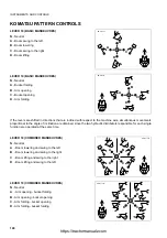
Page 107: ...r that the operator is allowed to move the machine only while seated in the correct driving position with locked seat and fastened safety belt q Before leaving the driver s seat lower the equipment to the ground engage the safety device to lock the controls and raise both joysticks towards the rear of the machine q Before starting work check the control pattern by carrying out short manoeuvres in ...

Page 108: ...f work lower the equipment to the ground and lock the controls again with button A LED on 6 Before rotating the seat to the driving position shift the joysticks in vertical position paying attention to the safety distance from the rear window If the end of stroke of the joysticks needs adjusting use the screws positioned on the front part of the same see 3 3 6 pos 4 JOYSTICK STROKE ADJUSTING KNOB ...

Page 109: ...to the angle of inclination are obtained since the two hydraulic distributors responsible for each single function are operated at the same time LEVER 18 COMBINED MANOEUVRES N Neutral A Arm opening Boom swing to the left B Arm opening Boom swing to the right C Arm folding Boom swing to the right D Arm folding Boom swing to the left LEVER 19 COMBINED MANOEUVRES N Neutral A Boom lowering Bucket fold...

Page 110: ...nal to the angle of inclination are obtained since the two hydraulic distributors responsible for each single function are operated at the same time LEVER 18 COMBINED MANOEUVRES N Neutral A Boom lowering and swing to the left B Boom lowering and swing to the right C Boom lifting and swing to the right D Boom lifting and swing to the left LEVER 19 COMBINED MANOEUVRES N Neutral A Arm opening bucket ...

Page 111: ...rn change control lever 20 has two positions q Pos 1 ISO PATTERN control system Lever in position B q Pos 2 OPTION PATTERN control system Lever in position C The control lever 20 is held in its position by means of a safety screw D When it is necessary to change the control pattern raise the mat and loosen the safety screw D until releasing the lever 20 completely Select the desired control patter...

Page 112: ...sing the machine make sure that both the steering wheel and the adjusting lever are locked Non compliance with these instructions may lead to serious accidents The lever 1 is positioned under the steering wheel and allows the latter to be adjusted according to the physical structure of the operator Different inclinations are possible and angular movements can be obtained after lifting the lever 1 ...

Page 113: ...ng to accompany them until they reach the desired position q At the end of digging operations with the backhoe always shift both joysticks back to the vertical position 3 ARM SUPPORT ADJUSTING KNOB WARNING q The operator must adjust the arm supports while seated in the driving position before starting work and with the machine completely still q Before carrying out this operation make sure that th...

Page 114: ...y the arrow B 2 After adjusting both joysticks make sure that their position is within the desired values It is also possible to adjust the stroke of the joysticks when they are not used and are in vertical position Once they have been lifted make sure that the safety distance between the joystick C and the rear window D is sufficient to avoid any contact approximately 60 mm If an adjustment shoul...

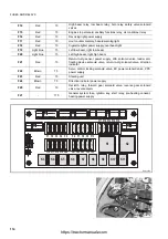
Page 115: ...lays 3 4 1 1 FUSES RKAB5420 1 RKAB5430 POSITION COLOUR CAPACITY A CIRCUIT INVOLVED F1 Light blue 15 Central front work lights F2 Light blue 15 Central rear work lights F3 Violet 3 Front left and rear right parking light parking light warning light instrument backlighting F4 Violet 3 Front right and rear left parking light cigarette lighter light F5 Red 10 Front horn F6 Light blue 15 Lateral rear w...

Page 116: ...loader arm floating device solenoid valve return to dig solenoid valve direction indicator F22 Brown 7 5 Servo control locking solenoid valve EC power solenoid valve PPC power supply F23 Red 10 Steering unit F24 Brown 7 5 Direction indicator power supply F25 Red 10 Declutch relay forward gear solenoid valve reverse gear solenoid valve reverse alarm F27 175 General system fuse ignition key start re...

Page 117: ...elay K11 Direction indicator power supply relay declutch K12 Machine functions relay K13 Start relay K14 Glow plug preheating relay K15 Multifunction unit K16 Electronic gearshift unit RKAB3270 K14 K15 RKAB3280 K12 K13 K16 RKAB5840 F1 F2 F3 F4 F5 F6 F7 F8 F9 F10 F11 F16 F17 F18 F19 F20 F21 F22 F23 F24 F25 F12 F13 F14 F15 15 15 10 15 15 10 10 10 10 10 10 10 3 3 7 5 7 5 7 5 5 10 15 15 7 5 7 5 10 K3 ...

Page 118: ... tables indicate the characteristics and the functions of the single fuses and relays 3 4 2 1 FUSES 3 4 2 2 RELAYS 1 RKAB6280 1 RKAB6290 2 POSITION COLOUR CAPACITY A CIRCUIT INVOLVED 1 Yellow 20 1st and 2nd fan speed power supply 2 Orange 40 rd fan speed power supply 3 Brown 7 5 Air conditioning compressor POSITION DESCRIPTION 4 rd fan speed relay 5 General heating relay 6 Air conditioning compres...

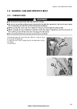
Page 119: ...g the hood lower the equipment to the ground and apply the parking brake q Before carrying out any maintenance operation inside the engine compartment park the machine on firm and flat ground lift the loader arm and engage the safety lock q Non compliance with these rules may lead to serious accidents After releasing the lock press the push button 1 raise the hood 2 and open it completely To close...

Page 120: ...ency door is not locked The cab s rear window can be opened completely once opened this window must be secured to the upper part of the cab parallel to the roof The side windows can be opened partially or completely even if the doors are completely closed These solutions are particularly useful during the summer since they ensure constant air circulation and therefore reduced stress for the operat...

Page 121: ... toward the outside of the cab After lifting the lever 3 push its end downwards in order to engage it in the upper coupling pin 5 as shown in Figure B If it is necessary to open the rear side windows completely proceed as follows 1 Release the lever 3 from the upper coupling pin 5 following the direction indicated by the arrow shown in Figure C 2 With the window open lower the lever 3 until engagi...

Page 122: ...ngaging the lever 3 with the lower 4 or upper 5 coupling pin q When the rear side windows are rotated towards the front of the machine in order to open them completely make sure that they are perfectly fixed in the relevant rubber elements 7 q Periodically lubricate the rubber elements 7 with specific greases in order to facilitate the coupling operation On request the cab access doors can be open...

Page 123: ... the flows that serve to defrost and defog the front window A radiator having the function to heat the air conveyed into the cab is installed beside the fan this is used in the cold season and receives the hot water necessary for the heat exchange directly from the engine cooling circuit The water supply flow is partialized or excluded by means of a cock operated by the knob 4 The intensity of the...

Page 124: ...ature is particularly high Ventilation and air change are achieved by means of a 3 speed fan which is built in the air conditioning system and assembled on the outside of the machine under the cab The ventilation can be adjusted via the selector 2 The ventilation and cooling system ensures air suction both from the outside and the inside of the cab Air suction from the outside is protected by mean...

Page 125: ...s min every 5 days max every 15 days q Before operating the air conditioner interrupt the circulation of hot water in the engine by rotating the valve 9 positioned in the engine compartment clockwise The air conditioner can be started by means of the switch 1 positioned on the side dashboard After starting the air conditioner LED on turn the knob 3 completely counterclockwise and adjust the ventil...

Page 126: ...ructure of the operator The adjustment of the suspension is carried out with the snap lever 3 and can be controlled by observing the position of the indicator 4 The operator must carry out this adjustment while seated the right suspension degree is reached when the indicator is positioned in correspondence with the seat frame If the indicator protrudes from the frame it is necessary to operate the...

Page 127: ...ically adapt to the physical structure of the operator The degree of suspension can be adjusted by rotating the knob 3 and checking the graduated scale on the knob itself The ideal position is reached when the weight indicated on the scale corresponds to the operator s weight In any case the operator can choose the degree of suspension at his sole discretion Turn the knob 3 clockwise to obtain a m...

Page 128: ...t position it on the appropriate hole provided on the left console 3 5 8 FIRST AID KIT CAUTION q Periodically make sure that the first aid kit contains the necessary disinfectants bandages medicins etc and check their condition and expiry date The first aid kit case 1 must be positioned inside the cab and precisely in the compartment provided on the left body side by the owner of the machine 3 5 9...

Page 129: ...5 10 STORAGE COMPARTMENT A storage compartment 1 has been obtained on the inner side of the right mudguard and can be reached after opening the door 2 The door is equipped with a lock 3 2 3 RKAB6260 2 RKAB6270 1 https tractormanualz com ...

Page 130: ...nd of the dashboard 11 the condition of the cab windows and the efficiency of lights work lights and direction indicators 10 the efficiency of the instruments and of the dashboard 3 6 1 2 DAILY CHECKS WARNING q Do not smoke while refuelling and adding oil and avoid using naked flames or non homologated lighting means to check the fuel or oil level in order not to cause fires q If some fuel oil or ...

Page 131: ...cks are intended to verify 1 if the safety locks of the front bucket and the backhoe control levers are engaged 2 the hand accelerator idling position 3 if the gearshift reverse gear lever is in neutral 4 if the parking brake is applied The following check is carried out by turning the ignition key to position to apply voltage to the control panel and check the functionality of the acoustic alarm ...

Page 132: ... sure that the gearshift and reverse gear levers are in neutral position A safety device does not allow the machine to be started with engaged gears or selected travel direction The machine is also equipped with an acoustic alarm that is activated when the operator with the engine running shifts the reverse gear lever from the neutral position with the seat rotated and not in the correct driving p...

Page 133: ...engine with a different power source make the electrolyte melt and make sure that it isn t frozen any more and that there are no leaks 1 Turn the key to the preheating position for maximum 15 seconds in the coldest weather The preheating time is determined according to the outside temperature and the ratio is approx 1 second for each degree below 0 C 2 Press the accelerator pedal completely and tu...

Page 134: ...e examined thoroughly and its cause must be immediately eliminated 3 6 4 HEATING THE HYDRAULIC OIL When warming up the engine especially in the cold season it is advisable to heat also the hydraulic system oil For this purpose when the coolant temperature has reached approximately 60 C proceed as follows 1 Press the servo control locking button LED off to release the controls see 3 3 2 pos 12 SERV...

Page 135: ... the instruments warm up the engine heat the hydraulic oil and make sure that the stabilizers have been raised and that both the front bucket and the backhoe are in transport position The control levers must be in the neutral position N At this point release the parking brake Select 1 the forward gear by rotating the gear lever 1 forward A or backward B and checking the selected gear on the front ...

Page 136: ...sengaged by means of the switch 1 positioned on the front dashboard It is normally used when the machine must move on muddy icy gravelly ground on slopes and in any situation in which it is difficult to move the machine The four wheel drive must be used even when the machine is provided with optional equipment to be employed as snowplough IMPORTANT q The four wheel drive is automatically engaged w...

Page 137: ...ied out are the following 1 Always check the work area for snow landslips gravel loose ground and anything that may suddenly modify the work conditions and the stability of the machine 2 When it is necessary to travel downhill the front bucket must always be directed downward in transport position 3 When loading or travelling uphill the front bucket must always be directed upward 4 When moving the...

Page 138: ...ng is sufficiently firm If it is necessary to work with the machine immersed in water make sure that the maximum depth does not exceed 50 cm and in any case that the engine cooling fan does not touch the water since it may get damaged or even break CAUTION q When working in water or on muddy ground lubricate the articulations more frequently than usual q After work remove any dirt or mud and lubri...

Page 139: ...e ladders and handles lock the cab 1 Park the machine on firm and level ground in a sufficiently wide space 2 Shift the reverse gear lever to position N and apply the parking brake 3 Rest the front bucket and the backhoe bucket onto the ground if this is not possible because the space is insufficient the backhoe must be folded in the transport position and secured with the appropriate lock 4 Press...

Page 140: ...nce of natural obstacles rotate the bucket in dumping position and thrust the teeth into the ground 2 Shift the reverse gear lever to position N and apply the parking brake 3 Operate the backhoe controls until the bucket teeth are in digging position and thrust them into the ground 4 Press the servo control locking button LED on 5 Stop the engine proceeding as described in 3 8 STOPPING THE ENGINE ...

Page 141: ...dle at a minimum speed of 1200 1300 rpm for about 5 minutes in order to allow it to cool down gradually before stopping it Before stopping the engine proceed as follows 1 Rest the front loader and backhoe equipment onto the ground 2 Shift the levers to the neutral position and connect the safety devices 3 Shift the hand accelerator lever to the idling position 4 Shift the reverse gear lever to pos...

Page 142: ...able for the wheel gauge of the machine q Position the ramps with a maximum inclination of 15 q Remove any trace of oil grease or ice from the ramps and the loading board q Do not change direction when the machine is already on the ramps if necessary go down and find the correct direction 1 The machine must get on the ramps with the front bucket 1 directed forward and lifted from the ground 2 Afte...

Page 143: ...rt the machine must be secured to the vehicle with closed doors and windows 1 Check the overall dimensions of the means of transport the height width and weight of the means of transport machine included must be compatible with the road and any tunnel underpass bridge electric or telephone line that may be found on the way 2 Keep to the regulations in force regarding signals speed limits road traf...

Page 144: ...2 COOLANT WARNING q The coolant containing antifreeze is flammable do not smoke and do not use naked flames during the checks and when preparing the mixture 1 Use only red permanent antifreeze suitable for aluminium radiators Pure red antifreeze must be diluted with water 50 to ensure protection down to 36 C 2 Do not mix different brands of antifreeze 3 The use of red permanent antifreeze requires...

Page 145: ...d reverse movements and operate all the bucket and backhoe cylinders slowly more than once These operations serve to warm up and fluidize the oil in the hydraulic circuit the transmission the axles and the brakes 3 10 5 PRECAUTIONS TO BE TAKEN AT THE END OF WORK 1 Remove mud and water completely from the machine body Park the machine on firm ground if the machine must be parked near banks or ditch...

Page 146: ...equires only the check of the level and the periodical change of the fluid For the relevant specifications see 4 3 FUEL COOLANT AND LUBRICANTS 2 Make sure that the cooling fan belt is in good conditions 3 Make sure that the fins of the radiator and of the heat exchanger are clean 4 Check the radiator cap gasket and spring in case of doubt regarding tightness and setting change the cap https tracto...

Page 147: ...chine is provided with automatic RETURN TO DIG device the horizontal parallel position of the bucket with respect to the ground is determined by the sensor 3 located on the cylinder and is reached when the sensor does not detect the rod 1 any longer In case of malfunction of the device check and if necessary carry out the required adjustments To adjust the sensor see 4 8 1 m ADJUSTING THE AUTOMATI...

Page 148: ...draulic system to accelerate the operations if such device is provided Once the device has been connected it lowers the arm completely and at the same time brings the bucket in perpendicular position with respect to the ground This is particularly useful for the operator since in this way the machine is ready for the successive loading phase For the correct use of the return to dig device see 3 3 ...

Page 149: ...me off always use gloves goggles and helmet q The change of the equipment must be carried out by two operators who must decide together the words and signals to be used during work q Avoid using your fingers to align the holes since the may be injured or even cut off q The described procedures are valid also for the coupling of the mechanical connections of the optional equipment 1 Position the bu...

Page 150: ...e safety belt before starting any manoeuvre q Always lower the stabilizers before starting any digging operation q Before starting work alert the persons in the vicinity by means of the horn integrated in the side dashboard or in the left backhoe control lever if the machine is equipped with backhoe servo controls 3 13 1 POSITIONING THE BUCKET ACCORDING TO THE WORK THAT MUST BE CARRIED OUT WARNING...

Page 151: ...or 1 Centre the machine with respect to the digging line IMPORTANT q If this is not possible because it is necessary to dig along walls or banks move the backhoe sideward see 3 13 3 SLIDING THE BACKHOE UNIT SIDEWARDS 2 Remove the boom anti rotation pin introduce it in the apposite hole and release the boom from the safety lock 3 Lower the front bucket 1 to the ground force this movement until lift...

Page 152: ...ting 3 Swing the boom 2 against the machine 4 Manoeuvre the bucket 3 and the arm 4 until the bucket teeth are perpendicular to the ground when arm and boom form an angle of approx 90 plant the bucket teeth onto the ground 5 Release the backhoe unit see 3 3 5 pos 8 BACKHOE SLIDING LOCK SWITCH 6 Make the unit slide by manoeuvring the arm CAUTION q Carry out this manoeuvre by operating the arm openin...

Page 153: ...filling of the bucket and therefore increase productivity 4 The removal depth must be correct and suitable to the type of ground excessive depth may lock the movements overload the engine and the pump and slow down the digging operations 5 To dump on heaps dump the bucket as soon as it gets near the dumping area the inertia resulting from the movement will ensure the compaction of the material wit...

Page 154: ... connections of the optional equipment 1 Position the bucket on level ground directing it so that the flat part of the bucket back rests on the ground 2 Remove first the tie rod pin 1 and then the arm connection pin 2 3 Change the bucket taking care to clean the pins and bushings perfectly and to grease the pins slightly before reinstalling them IMPORTANT q Install the arm connection pin first 4 P...

Page 155: ...place and to take the following measures 1 Clean the inside and the outside of the machine completely and very carefully retouching any scratch on the paintwork in order to avoid oxidation 2 Drain and change all the fluids of the hydraulic circuits and the lubricants axles reduction gears converter following the indications given in the maintenance instructions 3 Change all the filtering elements ...

Page 156: ...paring the engine for a long period of inactivity 7 Loosen the alternator fan and coolant pump belts 8 Reconnect the fuel pump intake pipe to the fuel tank 9 Seal the exhaust pipe and all the intake and breather openings with adhesive tape and vynil bags 10 Position a sign with the clear writing NO ENGINE OIL on the steering wheel and on the engine IMPORTANT q These operations must be repeated eve...

Page 157: ...ceeding as indicated in paragraph 3 6 2 STARTING THE ENGINE and make sure that the engine oil pressure warning light goes out when the starter has run for approx 5 seconds 10 After starting the engine let it idle for 15 minutes 11 Warm up the hydraulic cylinders by slowly lifting and extending all the equipment more than once 3 14 5 AFTER THE PERIOD OF INACTIVITY Considering that different periods...

Page 158: ...ut using only its motive power or in case of breakdown use a wire rope as shown in the figures on the right IMPORTANT q Before recovering the machine shift the gearshift reverse gear lever into neutral disengage the four wheel drive and release the parking brake 3 15 2 AFTER THE FUEL HAS RUN OUT Before starting the engine when the fuel has run out and therefore air has entered the fuel supply circ...

Page 159: ...volved part with plenty of water If the acid gets into the eyes immediately rinse with plenty of water and consult a doctor without delay q When working on the battery always wear goggles and gloves q When removing the battery disconnect first the earth cable when installing the battery connect first the positive cable q If a tool makes contact with the positive terminal and the machine structure ...

Page 160: ...ng aid must have greater capacity or at least the same capacity as the battery of the machine to be started q Make sure that the cables and pliers are neither corroded nor damaged q Make sure that the pliers hold the terminals firmly CONNECTING THE CABLES AND STARTING THE ENGINE 1 Make sure that the ignition key is in position 2 Connect the positive poles of the two batteries with each other A 3 C...

Page 161: ...arter pinion engages and then disengages Battery charge insufficient Charge the battery Starter makes engine run slowly Battery charge insufficient Faulty starter Charge the battery Change Starter disengages before engine has started Faulty cables Battery charge insufficient Check and repair Charge the battery Engine oil pressure warning light does not come on when engine is stopped ignition key i...

Page 162: ...at Change Change rings Clean valve carefully Pump delivery insufficient Oil level too low Suction filter clogged Faulty pump Top up Clean filter Change Overheating Damaged rings Faulty pump Oil level too low Dirty heat exchanger Damaged heat exchanger Remove disassemble and reassemble the unit Change Top up Clean Change Noisy converter Faulty pump Damaged bearings Change Remove and change Lack of ...

Page 163: ...ther causes Change Check pipes connections fuel and injection pumps Bleed circuit Contact Dealer Engine overheats Radiator clogged Insufficient tension of water pump and fan belts Low coolant Air filters clogged Clean fins Check and adjust belt tension Top up Clean or change filters Engine power insufficient Impurities or water in fuel supply circuit Fuel filter clogged Air filters clogged Clean a...

Page 164: ...162 THIS PAGE WAS INTENTIONALLY LEFT EMPTY https tractormanualz com ...

Page 165: ...MAINTENANCE 163 https tractormanualz com ...

Page 166: ...and change the oil in a clean place and prevent any impurities from getting into the tank q Before carrying out any maintenance operation hang warning plates on the ignition switch the control levers and the cab doors to prevent anyone from starting the engine q When performing maintenance operations always take the precautions indicated on the safety plates applied to the machine q Instructions f...

Page 167: ...equently to avoid any clogging of the fins 3 Change the diesel oil filter more frequently than usual 4 Clean the electrical components especially the starter and the alternator to avoid any accumulation of dust q Never mix oils of different brands Do not top up with any oil different from those used in the machine If necessary drain the tanks and fill them with the oil of the new brand https tract...

Page 168: ...the coolant level in the expansion tank daily and top up when necessary q The coolant containing antifreeze is flammable do not use naked flames near the coolant and do not smoke while topping up TANK RESERVOIR SPECIFICATIONS Engine oil SAE 15W 40 Specifications API CI 4 ACEA E7 Hydraulic system oil SAE 10W 30 Specifications API CF CF2 CD Biodegradable hydraulic system oil Only for machines in whi...

Page 169: ...w condensate from the drum bottom q If fuel runs out or if the fuel filter has been replaced it is necessary to bleed the circuit 4 2 2 NOTES REGARDING THE HYDRAULIC SYSTEM q Be extremely careful when performing maintenance operations on the hydraulic system since soon after work the oil is very hot The circuit is pressurized not only during work but also at the end of work q The maintenance opera...

Page 170: ...of any optional equipment contact your Komatsu Dealer q If any electric welding operation has to be carried out disconnect the battery and the alternator 4 2 4 NOTES REGARDING LUBRICATION q Lubrication makes the operations carried out with the machine and work equipment smoother while preventing wear and the noise that may be produced if the joints are dry Lubrication is to be carried out with gre...

Page 171: ...SCRIPTION Q ty CHANGE INTERVAL Hydraulic oil drain filter 42N 62 15470 Cartridge 1 EVERY 500 HOURS OF OPERATION Engine oil filter EA504074043 Cartridge 1 Fuel filter EA504073234 Cartridge 1 Converter oil filter CA0040952 Cartridge 1 EVERY 1000 HOURS OF OPERATION Air filter 848101189 848101190 Main cartridge Safety cartridge 1 1 WHEN REQUIRED WHEN REQUIRED Front bucket 312204054 801580085 801703012...

Page 172: ...CF2 98 40 Hydraulic system with biodegradable oil see 4 3 1 98 40 Front axle Differential OIL UTTO FLUID 10 5 10 5 Final reduction gear ea 1 3 1 3 Rear axle Differential 10 5 10 5 Final reduction gear ea 1 3 1 3 Hydraulic transmission OIL GM DEXRON II D DEXRON is a registered trademark of General Motors Corporation 20 20 Braking system 0 8 0 8 Fuel tank DIESEL OIL 150 Engine cooling system PERMANE...

Page 173: ...cuit in the transmission in the axles and in the brakes First filling quantity total quantity of oil including the oil for the components and pipes Oil change quantity quantity of oil necessary to fill the system or unit during the normal inspection and maintenance operations ASTM American Society of Testing and Materials SAE Society of Automotive Engineers API American Petroleum Institute UTTO Un...

Page 174: ...for the engine the transmission the braking system etc q Before introducing biodegradable oil in the hydraulic system empty the system completely disconnecting the cylinders and all the parts that may contain conventional oil and replace the drain filter with a new one Start the engine and let it idle without using the work equipment wait until the oil reaches a temperature of at least 40 C then s...

Page 175: ...table is not valid for screws or nuts that must fasten parts made of nylon or similar materials onto washers or components made of nylon or nonferrous metals or requiring specific driving torques RYA02980 Threaddiamete r a mm Pitch mm Wrench size b mm 8 8 10 9 kgm Nm kgm Nm 6 8 10 12 14 1 1 25 1 5 1 75 2 10 13 17 19 22 0 96 0 1 2 3 0 2 4 6 0 5 7 8 0 8 12 5 1 9 5 1 23 2 45 4 9 77 8 122 13 1 3 0 15 ...

Page 176: ...upport screws Rear support screws 20 4 1 20 4 1 200 9 8 200 9 8 Wheels Front Rear 81 6 1 81 6 1 800 9 8 800 9 8 Front bucket Teeth 16 1 157 9 8 Backhoe bucket Central teeth Side teeth 16 1 16 1 157 9 8 157 9 8 Engine and transmission Front support central screw Rear support central screw 20 1 20 1 196 9 8 196 9 8 RKA12600 a Thread diameter mm a Wrench size mm DRIVING TORQUE kgm Nm 9 16 18 11 16 16...

Page 177: ...ubricant to be used is indicated in the lubricant chart see 4 3 FUEL COOLANT AND LUBRICANTS check change 1 2 12 3 4 5 6 7 8 11 15 14 9 18 17 10 13 42N 93 12840 1 2 3 4 5 6 7 11 9 8 10 12 13 14 15 17 12 13 14 15 17 18 10 11 500h 10h 50h 250h 1000h 2000h 16 18 16 RKA17230 Hydraulic oil Grease Engine oil Transmission oil Brake oil https tractormanualz com ...

Page 178: ...ION DIAGRAM q The points indicated are symmetrical and must be lubricated every 10 hours of operation q The fork sliding bars and the safety pins must be lubricated with grease only to protect them from oxidation q The fork joints A must be lubricated only if the forks are used 10 h A RKA15470 Grease Grease https tractormanualz com ...

Page 179: ...RAM front bucket quick couplings IMPORTANT q For the other greasing points see 4 5 1 LUBRICATION DIAGRAM q The points indicated are symmetrical and must be lubricated every 10 hours of operation RWAA9200 10 h Grease https tractormanualz com ...

Page 180: ...LUBRICATION 178 4 5 4 LUBRICATION DIAGRAM offset device IMPORTANT q For the other greasing points see 4 5 1 LUBRICATION DIAGRAM RKA14130 10 h Grease https tractormanualz com ...

Page 181: ...y in case of failures or anomalies even if the time interval prescribed for their change has not elapsed yet If the pipe clamps show signs of deterioration like deformations or cracks change them together with the pipes In addition to the periodical change of the components listed in the following page the inspections described here below are to be carried out on the hydraulic pipes In case of ano...

Page 182: ...ee the spare parts catalogue q When changing pipes always change O rings gaskets and analogous components 4 6 1 1 FUEL SYSTEM No Safety related components that periodically need changing Q ty Change interval 1 Fuel pipe Fuel tank Fuel pump 1 Every 2 years or 4000 hours whichever occurs firs 2 Fuel pipe Injection pump Fuel tank 1 RKA14150 2 1 https tractormanualz com ...

Page 183: ... 6 1 2 DELIVERY HYDRAULIC SYSTEM No Safety related components that periodically need changing Q ty Change interval 1 Hydraulic pipe Loader distributor backhoe distributor 1 Every 2 years or 4000 hours whichever occurs firs RKA14160 1 https tractormanualz com ...

Page 184: ... related components that periodically need changing Q ty Change interval 2 Hydraulic pipes Cylinders loader arm 4 Every 2 years or 4000 hours whichever occurs firs 3 Hydraulic pipes Cylinders loader bucket 4 4 Hydraulic pipes Cylinders 4in1 bucket 4 RKA16920 4 4 4 2 2 2 3 4 3 3 https tractormanualz com ...

Page 185: ...fety related components that periodically need changing Q ty Change interval 5 Hydraulic pipes Cylinder backhoe boom 2 Every 2 years or 4000 hours whichever occurs firs 6 Hydraulic pipes Cylinder backhoe boom 2 7 Hydraulic pipes cylinder backhoe bucket 4 RKA14180 7 6 5 https tractormanualz com ...

Page 186: ...ANGE OF THE SAFETY RELATED COMPONENTS 184 4 6 1 5 OPERATOR S SAFETY No Safety related components that periodically need changing Q ty Change interval 1 Safety belt 1 Every 4 years 1 RWA31240 https tractormanualz com ...

Page 187: ...CKING THE COOLANT LEVEL 197 c CHECKING THE FUEL LEVEL 198 d CHECKING THE ENGINE OIL LEVEL 198 MAINTENANCE EVERY 10 HOURS OF OPERATION a LUBRICATING THE JOINTS 199 MAINTENANCE AFTER THE FIRST 50 HOURS OF OPERATION Only for machines in which synthetic biodegradable oil type HEES is used Operations to be carried out together with those prescribed at point 4 8 6 MAINTENANCE EVERY 50 HOURS OF OPERATION...

Page 188: ...thetic biodegradable oil type HEES is used 217 g CLEANING THE OUTSIDE OF THE RADIATOR 218 h CLEANING THE OUTSIDE OF THE A C CONDENSER only for machines with air conditioner 219 MAINTENANCE EVERY 1000 HOURS OF OPERATION a CHANGING THE FRONT AXLE OIL 220 b CHANGING THE REAR AXLE OIL 221 c CHANGING THE HYDRAULIC TRANSMISSION OIL 222 d CHANGING THE HYDRAULIC TRANSMISSION OIL FILTER 223 MAINTENANCE EVE...

Page 189: ...see 3 5 1 ENGINE HOOD To clean the primary element proceed as follows 1 Release the safety retainer 1 moving it toward the outside 2 Turn the cover 2 counterclockwise by approximately 12 5 3 Lift the cover 2 and extract the filtering element 3 4 Slightly strike the filtering element 3 on the palm of your hand in such a way as to remove the dust and blow compressed air on the inner surface keeping ...

Page 190: ...e that all the filter components are perfectly secured 4 Push the safety lock 1 towards the inside 4 8 1 b CHECKING AND CLEANING THE CAB AIR FILTER WARNING q Wear safety goggles during the cleaning operations The air suction for the ventilation of the cab is protected by a filter positioned on the right side of the cab This filter blocks all the impurities contained in the air and must be cleaned ...

Page 191: ...to the suction duct 4 Put back the filtering element 3 the container of the storage compartment 2 and close the door 1 IMPORTANT q If the filtering element is excessively clogged or damaged change it with a new one 4 8 1 d CHECKING THE DETERGENT LEVEL IN THE WINDSHIELD WASHER RESERVOIR The reservoir 1 is positioned inside the engine compartment and contains detergent for the front and rear windshi...

Page 192: ...ee 4 3 FUEL COOLANT AND LUBRICANTS CAUTION Inject grease until all the residual old grease has come out After lubrication remove all the grease that has come out and clean the area 4 8 1 g FUSES AND RELAYS CHECK AND CHANGE IMPORTANT q When changing a fuse make sure that the ignition key is in position q If the fuses are oxidized corroded or do not fit perfectly in their seat replace them only with...

Page 193: ...aches the maximum level 5 Press the left brake pedal thoroughly and keeping it pressed loosen the drain screw 1 of the corresponding brake until the pedal reaches the end of stroke Use a 13 mm wrench 6 While keeping the pedal completely pressed tighten the drain screw 1 7 Release the brake pedal wait a few seconds and repeat the operations described above until no air bubbles can be noticed in the...

Page 194: ...he conditions of the articulated heads 3 if a considerable slack is observed change them immediately 4 8 1 j CHECKING THE BRAKING EFFICIENCY IMPORTANT q During running in check the braking efficiency after the first 100 hours of operation q Perform this check on firm level ground with no people or obstacles around This check must be carried out after setting the work equipment in the travel or tra...

Page 195: ...ign the machine in travel position on a straight road section and proceed up the slope with 20 gradient 3 Stop the machine with the service brake shift the reverse gear lever 1 to the neutral position N and stop the engine 4 Apply the parking brake lock position release the service brake slowly and make sure that the machine does not move ADJUSTMENT 1 With the engine off release the brake lever an...

Page 196: ... in this position Use a 22 mm wrench 4 8 1 m ADJUSTING THE AUTOMATIC RETURN TO DIG DEVICE OF THE FRONT BUCKET if installed The device for the automatic return of the front bucket to the digging position automatically brings the front bucket to the loading position when it is lowered to the ground The sensor is positioned on the right dumping cylinder and determines the horizontal position of the b...

Page 197: ...between 0 5 and 1 0 mm If the slack exceeds the values indicated loosen the screws 3 remove the adjusting plate 4 and remove one or more washers 5 from both the adjusting points according to the needs Once they have been removed the washers 5 must be positioned again between the adjusting plate 4 and the screws 3 During the adjustment check the condition of the adjusting element 2 and change it im...

Page 198: ...given in the table on the right If the machine contains synthetic biodegradable oil type HEES the filter must be changed after the first 50 hours of operation 4 8 2 b CHANGING THE HYDRAULIC OIL Change the hydraulic oil in the tank according to the intervals indicated in the table on the right On machines containing synthetic biodegradable oil type HEES change the oil after the first 500 hours of o...

Page 199: ...he warning plates 8 Make sure that the ladders and handles used to reach the driver s seat and the inside of the cab are clean 4 8 3 b CHECKING THE COOLANT LEVEL WARNING q Do not remove the radiator cap the coolant level must be checked with cold engine through the expansion tank The coolant level must be checked on the expansion tank 1 when the engine is cold and must be included between the MIN ...

Page 200: ...he filler cap 2 thoroughly and lock it 4 8 3 d CHECKING THE ENGINE OIL LEVEL WARNING q Soon after the machine has been stopped the engine is very hot and may cause burns let the engine cool down before carrying out any check The dipstick 1 can be reached after opening the engine hood See 3 5 1 ENGINE HOOD The oil level must be checked with cold engine and the machine parked on level ground The oil...

Page 201: ...OLANT AND LUBRICANTS and 4 5 1 LUBRICATION DIAGRAM IMPORTANT q As a general rule it is important to consider that each cylinder is provided with two grease nipples positioned on the couplings and that each pin serving as fulcrum point for a movement is provided with at least one grease nipple POINTS TO BE LUBRICATED ON THE FRONT LOADER RKA16950 7 2 9 8 12 11 10 6 1 3 5 4 1 4in1 bucket opening fulc...

Page 202: ...n cylinder base pin 1 point 6 Bucket cylinder base pin 1 point 7 Telescopic arm extension cylinder head pin 1 point 8 Bucket cylinder head and lever tie rod coupling pin 3 points 9 Tie rod bucket coupling pin 2 points 10 Bucket fulcrum pin 1 point 11 Lever fulcrum pin 1 point 12 Arm fulcrum pin 1 point 13 Arm cylinder head pin 1 point 14 Boom fulcrum pin 2 points 15 Boom swing cylinder head pin 2 ...

Page 203: ...n q If it is necessary to top up stop the engine and eliminate the residual pressure from the equipment circuits by moving the controls more than once and from the tank by slowly loosening the filler cap 2 The oil level must be visible through the window 1 provided on the tank and must be included between the MIN and MAX marks If the level is near the MIN reference mark open the engine hood see 3 ...

Page 204: ...d make sure that there are no air leakages from the pipe that connects the radiator to the expansion tank If the problem persists contact your Komatsu Dealer 4 8 6 c CHECKING THE BRAKING SYSTEM OIL LEVEL This operation must be carried out when the warning light 1 on the front instrument panel comes on see 3 3 1 pos 8 LOW OIL PRESSURE OR BRAKING SYSTEM FAILURE WARNING LIGHT The brake fluid reservoi...

Page 205: ...ase nipples by applying the grease pump filled with the prescribed grease See 4 3 FUEL COOLANT AND LUBRICANTS and 4 5 1 LUBRICATION DIAGRAM Once the lubrication procedure has been carried out make sure that all the points have been lubricated and remove the used grease that may have spread out of the joints IMPORTANT q If the machine is used in difficult conditions carry out this operation more fr...

Page 206: ...ANT AND LUBRICANTS e 4 5 1 LUBRICATION DIAGRAM A lubrificazione ultimata asportare il grasso inquinato fuoriuscito dagli snodi e dall attacco centrale 4 8 6 f CHECKING THE TYRE PRESSURE WARNING q Inflate the tyres only after positioning them in a protection cage q Stand beside the tyre to inflate it q Do not exceed the pressure values indicated in the technical data sheet see 5 1 TECHNICAL DATA Th...

Page 207: ...t be carried out with full tank in order to prevent air from entering the fuel circuit The condensate must be drained at the end of work before the engine has completely cooled down in order to prevent it from freezing if the temperature drops considerably The water separator can be reached after removing the engine hood see 3 5 1 ENGINE HOOD Drain the condensate by loosening the plug 1 waiting un...

Page 208: ...nd 4 8 11 MAINTENANCE EVERY 1000 HOURS OF OPERATION For checks and adjustments contact your Komatsu Dealer 4 8 8 MAINTENANCE EVERY 250 HOURS OF OPERATION Carry out the following operations together with those to be performed every 50 HOURS 4 8 8 a CHECKING THE ALTERNATOR FAN BELT WARNING q Carry out this checking and maintenance operation only with cold engine The belt 1 can be reached after openi...

Page 209: ...re of the section between the compressor 2 and the pulley 3 If the pressure exerted is approximately 10 kg the resulting deflection must be approx 5 6 mm When the belt is new the resulting deflection must be approx 4 mm If the resulting deflection exceeds the values indicated proceed as follows 1 Remove the belt guard 4 2 Loosen the screw 5 that fastens the cam 6 3 Loosen the screw 7 that fastens ...

Page 210: ...in each cell must be about 6 mm above the plate edge if necessary remove the cell caps and top up using exclusively distilled water If on the contrary the level is low because some fluid has been spilled add electrolyte with concentration suitable for the ambient temperature see 3 10 3 BATTERY NOTE q When adding distilled water or electrolyte do not exceed the level indicated This would shorten th...

Page 211: ...ng the prescribed oil see 4 3 FUEL COOLANT AND LUBRICANTS Use a 1 2 square wrench 4 8 8 e CHECKING THE REAR AXLE OIL LEVEL WARNING q Carry out this check with the machine parked on a level surface and the work equipment resting on the ground DIFFERENTIAL This check is visual and serves to verify if the lubricant reaches the hole 1 if necessary top up using the prescribed oil see 4 3 FUEL COOLANT A...

Page 212: ...h the engine idling and the oil at running temperature The oil must always reach the maximum level or be very near it Top up through the opening used for the dipstick 1 using the prescribed oil see 4 3 FUEL COOLANT AND LUBRICANTS 4 8 8 g CHECKING THE WHEEL NUT DRIVING TORQUE This check serves to restore the tightening torque of the wheels on the hubs The torque can be checked by means of a torque ...

Page 213: ... change will make the ground slippery therefore use anti slip shoes and immediately remove any trace of oil from the floor q Oils filters the coolant and the battery are considered special waste and must be collected and disposed of according to the regulations in force When changing the engine oil change also the filter see 4 8 10 b CHANGING THE ENGINE OIL FILTER Proceed as follows 1 Open the eng...

Page 214: ...ts against the seal 4 Give another half turn by hand Start the engine make sure that there are no leakages and that the low oil pressure warning light goes out IMPORTANT q Do not use the wrench to lock the filter in order to avoid damaging the filter itself and causing oil leakages 4 8 10 c CHANGING THE HYDRAULIC SYSTEM OIL FILTER WARNING q Soon after the machine has been stopped the hydraulic oil...

Page 215: ... release any residual pressure 4 Remove the cap 5 and gather the oil that flows out approx 1 2 litre Use a 19 mm socket wrench 5 Remove the filter housing 6 and collect the residual oil from the inside approx 1 litre Use a 42 mm socket wrench 6 Remove the cartridge 7 and carefully clean the housing 7 Clean the contact surface between the seal and the filter support 8 Install a new cartridge in the...

Page 216: ...used for simple digging operations On new machines change the filter after the first 100 150 hours of operation and for the successive changes keep to the indications given in the table on the right 0 20 40 60 80 100 500 100 800 Breaker operating ratio Replacement interval H Replacement interval for element RWA10710 https tractormanualz com ...

Page 217: ...crew thoroughly until the filter rests against the seal 4 Give another half turn by hand 5 Bleed the fuel circuit BLEEDING THE CIRCUIT After refuelling proceed as follows 1 Turn the ignition key to position 2 Loosen the bleeder screw 3 on the filter housing head 2 3 Operate the fuel pump 4 and keep it running until no more air can be observed in the fuel that flows out of the filter head 2 Tighten...

Page 218: ...level on the indicator is above the reserve mark Its purpose is to let out any impurity and condensate that may have accumulated in the fuel tank without letting air into the engine fuel supply lines 1 To let the condensate flow out loosen the drain plug 1 and wait until no more water is present in the fuel that flows out IMPORTANT q The tank must be drained before starting the engine at temperatu...

Page 219: ...ected and disposed of according to the regulations in force This operation serves to let the condensate accumulated on the tank bottom flow out of the tank itself for this purpose carry out the following operations in the given sequence 1 Open the engine hood see 3 5 1 ENGINE HOOD and loosen the filler cap 1 to release any residual pressure from the tank 2 Remove the drain plug 2 until all the con...

Page 220: ...ic detergents available on the market can certainly be used provided that the instructions given on the package are followed and that the washed parts are carefully dried After washing put back the front guard 1 IMPORTANT q Do not use products containing even a slight quantity of oily substances since these facilitate the adhesion of dust which affects the heat exchange adversely q Clean the outsi...

Page 221: ...m washing cycle the specific products available on the market can certainly be used provided that the instructions given on the package are followed and that the washed parts are carefully dried IMPORTANT q Do not use products containing even a slight quantity of oily substances since these facilitate the adhesion of dust which affects the heat exchange adversely q Carry out this operation wheneve...

Page 222: ...et the used oil flow out completely gathering it into a container with suitable capacity While the oil flows out remove the plug 1 Use a 17 mm wrench 2 Once the oil has been drained put back the drain plug 2 and add oil of the prescribed type through the hole 1 until reaching the level corresponding to the lower edge of the hole itself 3 Put back the plug 1 FINAL REDUCTION GEARS 1 Move the machine...

Page 223: ...rench 2 Once the oil has been drained put back the drain plug 2 and add oil of the prescribed type through the hole 1 until reaching the level corresponding to the lower edge of the hole itself IMPORTANT q With this operation both axle shafts are filled with oil before checking the level definitively and putting back the plug wait a few minutes in order to allow the oil to be distributed uniformly...

Page 224: ...hange also the filter see 4 8 11 d CHANGING THE HYDRAULIC TRANSMISSION OIL FILTER Proceed as follows 1 With the machine at operating temperature stop the engine open the engine hood see 3 5 1 ENGINE HOOD and extract the dipstick 2 2 Remove the drain plug 1 and let the oil flow into a container with suitable capacity Use a 1 2 square wrench 3 Remove the filter 3 and change it see 4 8 11 d CHANGING ...

Page 225: ...st 250 hours of operation and successively every 1000 hours Carry out this operation whenever the transmission oil is changed Proceed as follows 1 Raise the front mat and remove the cover 1 Use a 13 mm wrench 2 Unscrew and remove the old filter 2 by means of the special wrench provided 3 Clean the contact surface between the seal and the filter support 3 4 Lubricate the seal fit it in its seat and...

Page 226: ...oolant and the battery are considered special waste and must be collected and disposed of according to the regulations in force 1 Open the engine hood see 3 5 1 ENGINE HOOD and slowly loosen the filler cap 1 to release any residual pressure from the tank then remove it 2 Remove the drain plug 2 and let the oil flow out gathering it into a container with suitable capacity Use a 41 mm wrench 3 Remov...

Page 227: ...ch piston move several times in order to bleed the system Stop the machine in maintenance position check the oil level again and top up if necessary Always use oil of the prescribed type see 4 3 FUEL COOLANT AND LUBRICANTS 14 Close the engine hood IMPORTANT q Do not start the engine with empty tank since this would certainly damage the pump q In machines equipped with demolition hammer hydraulic o...

Page 228: ...force IMPORTANT q The change of the permanent coolant does not require any washing cycle to descale the circuit 1 Open the engine hood see 3 5 1 ENGINE HOOD 2 Loosen and remove the upper cap 1 of the radiator 3 Open the drain cock 2 of the radiator and let the fluid flow out gathering it into a container with suitable capacity Drain the expansion tank 3 while the fluid flows out 4 Close the drain ...

Page 229: ...t with the machine positioned on level ground and parking brake applied Drain the oil and wash the system proceeding as follows 1 Apply a small pipe for the collection of the oil to the drain screws 1 and loosen them Use a 13 mm wrench 2 Remove the front guard 2 and the cap 3 3 Operate the brake pedals connected with each other until the oil contained in the reservoir 3 runs out 4 Fill the reservo...

Page 230: ...ystem is very dangerous If it is sprayed into the eyes or in case of contact with the skin it may cause blindness or frostbite To avoid any explosion do not generate sparks and do not use naked flames near the air conditioner q Oils filters the coolant and the battery are considered special waste and must be collected and disposed of according to the regulations in force q Maintenance on the air c...

Page 231: ...S AND DAMPING ELEMENTS This procedure must be carried out by qualified personnel Have this operation performed by your Komatsu Dealer 4 8 13 b CHECKING AND ADJUSTING THE ENGINE VALVE CLEARANCE AND THE INJECTION TIMING ADVANCE Since these checks and adjustment operations require the use of special tools have these operations carried out by qualified personnel supplied by your Komatsu Dealer https t...

Page 232: ... the regulations in force q Have the dewatering filter changed only by specialized personnel and for this purpose contact your Komatsu Dealer The filter 1 must be changed every 4000 hours of operation or every 2 years whichever occurs first The filter must also be changed whenever operations involving the opening of the air conditioning system are performed 4 8 14 b CHECKING THE OPERATING CONDITIO...

Page 233: ...TECHNICAL SPECIFICATIONS 231 https tractormanualz com ...

Page 234: ... 1 STANDARD OVERALL DIMENSIONS 5 1 1 1 OVERALL DIMENSIONS WITH STANDARD ARM 5 1 1 2 OVERALL DIMENSIONS WITH TELESCOPIC ARM 2190 2175 6035 1670 2900 200 3650 2420 RKA17020 2420 200 2900 3880 RKA17030 2190 2175 1670 6035 https tractormanualz com ...

Page 235: ...URBOCHARGED ENGINE Komatsu diesel engine model S4D104E 3 Maximum power 2200 rpm EEC 80 1269 kW 74 Maximum torque 1400 100 rpm EEC 80 1269 Nm 398 ELECTRICAL SYSTEM Alternator 12V Electrical output 95 A Grounding negative Battery 160 12V Starter kW 3 0 TRAVEL SPEED calculated with 16 9 28 tyres and engine at 2200 rpm FORWARD REVERSE GEARS 1a 2a 3a 4a R1 R2 R3 R4 km h 5 5 9 20 37 7 5 5 9 20 37 7 http...

Page 236: ... 10 16 9 28 PR12 ISGT Good Year bar 2 20 16 9R28 XM37 Michelin bar 3 10 440 80 R28 Nokian bar 3 20 REAR TYRES SIZE MAKE INFLATION PRESSURE Recommended 16 9 24 PR12 ISGT Good Year bar 2 60 16 9 R24 XM37 148A8 145B Michelin bar 3 10 16 9 28 PR12 ISGT Good Year bar 2 60 16 9R28 XM37 Michelin bar 3 10 440 80 R28 Nokian bar 3 20 https tractormanualz com ...

Page 237: ... on firm and flat ground 5 1 3 1 SYMBOL TABLE A Standard arm length L 2200 mm B Telescopic arm completely retracted C Telescopic arm completely extended D Standard operating weight E Standard backhoe bucket width and weight W 600 mm kg 160 F Operating hydraulic pressure G Lowered stabilizers P Lifting capacity Z Distance of the lifting point from the ground X Distance between the boom swing axis a...

Page 238: ... 0 1 m 24 5 MPa 245 Bar W 600 mm 160 Kg 8040 Kg D F E G A B C W 990 990 990 700 990 990 990 675 990 990 990 650 990 990 990 620 990 990 990 520 990 990 990 500 990 990 990 475 990 990 990 450 990 990 820 350 990 990 800 340 990 990 775 325 990 990 750 300 1000 Kg RKA17150 Z X P 2200 Min Max https tractormanualz com ...

Page 239: ...TECHNICAL DATA 237 5 1 3 3 LIFTING CAPACITIES BOOM WITH OFFSET DEVICE https tractormanualz com ...

Page 240: ...238 THIS PAGE WAS INTENTIONALLY LEFT EMPTY https tractormanualz com ...

Page 241: ...AUTHORISED OPTIONAL EQUIPMENT 239 https tractormanualz com ...

Page 242: ...l on a firm and flat surface q When the operations are carried out by two or more operators decide the communication signals in advance and respect them during work q Use a crane to handle objects weighing more than 25 kg q Always support any heavy part before removing it When lifting heavy parts be always careful to the position of the centre of gravity of the object being handled q It is dangero...

Page 243: ...amped on the forks See 6 4 PALLET FORKS a Measure referred to the equipment diameter e Measure referred to the equipment length EQUIPMENT MAX WEIGHT kg MAX DIMENSIONS MAX CAPACITY ISO m3 MAX OPERATING PRESSURE bar MAX FLOW RATE l min Width mm Height mm Front bucket 450 2320 940 1 1 Front 4 in1 bucket 750 2340 1015 1 0 200 75 Forks on front bucket 190 q q T Pallet forks 320 1800 800 t Backhoe bucke...

Page 244: ...w the coupling pins completely 2 Start the machine and position the equipment carrier 2 perpendicular to the equipment to be installed 3 Using the bucket control lever 3 position the fixed rod 4 of the equipment carrier under the upper seats 5 on the bucket 6 4 Lift the arm 7 and engage the fixed rod 4 in the upper seats 5 lift the bucket slightly 5 Turn the lever 1 completely counterclockwise to ...

Page 245: ...eeding as follows 1 Turn the ignition key to position 2 Press the servo control locking button and make sure that the LED is off release position see 3 3 2 pos 12 SERVO CONTROL LOCKING BUTTON 3 Operate the loader arm control lever and the 4in1 bucket opening and folding buttons more than once 4 Turn the ignition key to position q If any oil has been spilled wipe it up immediately in order to preve...

Page 246: ...f two hydraulic cylinders 1 controlled by an additional distributor The opening and folding of the bucket are controlled via two push buttons 5 and 6 positioned on the loader control lever 7 which also maintains all its normal functions see 3 3 5 pos 4 FRONT LOADER CONTROL LEVER 6 3 2 SAFETY DEVICES The 4in1 bucket is provided with teeth guard 3 If the bucket is equipped with pallet forks the safe...

Page 247: ...and eliminate the residual pressure from the hydraulic circuits by proceeding as follows 1 Turn the ignition key to position 2 Press the servo control locking button and make sure that the LED is off release position see 3 3 2 pos 12 SERVO CONTROL LOCKING BUTTON 3 Operate the loader arm control lever and the 4in1 bucket opening and folding buttons more than once 4 Turn the ignition key to position...

Page 248: ...ading on high surfaces by opening the bucket instead of overturning it vertical unloading 3 Handling logs branches etc with the grapple function opening and closing by using the teeth provided on the mobile jaw 4 to grasp them 4 Flushing and levelling with open bucket IMPORTANT q To flush the ground open the bucket and move the machine forward working with the fixed part of the bucket q To level t...

Page 249: ... The allowed load is generally stamped on the forks 6 4 1 DESCRIPTION They are usually applied to the 4in1 bucket and when they are not used they must be overturned towards the back of the machine and secured with the safety pins provided The pallet forks 1 make it possible to use the machine as a normal lift truck and the controls to lift and oscillate them are the same used to control the standa...

Page 250: ...the increased dimensions of the machine and learn how to use the fork controls q The forks protrude beyond the bucket outline and therefore it is necessary to be very careful when manoeuvring the machine especially in reduced spaces q After forking the material before lifting the load move the forks in such a way as to lift their prongs and therefore prevent the load from slipping DANGER q When th...

Page 251: ...em in the supports 5 as shown in Fig B CAUTION q During work avoid keeping the forks as represented in Figure A since they may make contact with the engine hood 3 Put back the pins 3 and the safety pins 4 4 Make sure that when they are overturned in rest position the forks are firmly secured inside their respective supports 5 If any slack should be observed between the forks and the safety pin 3 i...

Page 252: ...n and remove the screws 9 that fasten the slide bar 2 4 Hold one of the supports 8 and withdraw the slide bar 2 repeat the same operation for the other support 6 4 5 INSTALLING THE FORKS To install the pallet forks repeat the procedure described for the removal in the reverse order taking the same precautions 6 4 6 MAINTENANCE No specific maintenance operation is required for this device except fo...

Page 253: ...ides The sliding of the arm is achieved by means of a double acting cylinder controlled by an additional distributor The movement of the telescopic arm is achieved via the buttons 3 and 4 positioned on the right joystick lever The movements of the main equipment remain unchanged see 3 3 5 pos 18 19 BACKHOE CONTROL LEVERS The movements of the telescopic arm are as follows 1 Retraction of the arm ob...

Page 254: ... must be positioned as shown in Fig B 6 5 3 USING THE TELESCOPIC ARM WARNING q Before releasing and extending the arm make sure that the stabilizers rest on firm ground q If possible work with the backhoe centered on the guides and unload the material as near the machine as possible q If it is necessary to work with misaligned backhoe or with the backhoe completely shifted on the guides operate sl...

Page 255: ...on key q Adjust the screws and guides one by one q Do not place tools in the space between the safety locks and the arm 1 Position the machine on flat ground and lower the stabilizers 2 Lift the boom fold the bucket completely and extend the telescopic part 7 completely 3 Fold the arm until the slide guides 8 are perpendicular to the ground and in any case positioned so that the extending part is ...

Page 256: ... turn and lock them with the lock nuts 10 8 Start the machine extend and retract the telescopic arm more than once to make sure that it slides correctly CAUTION q The wear limit allowed for the rubber blocks is represented by the minimum engagement of the adjusting dowels 9 in the lock nuts the rubber blocks must be replaced when the heads of the dowels 9 are 5 mm back with respect to the lock nut...

Page 257: ...loor The movements of the levers described at point 3 3 5 pos 18 19 BACKHOE CONTROL LEVERS remain unchanged The hammer is operated by pressing the foot operated button 1 since in this way pressurized oil is conveyed into the circuit when the foot operated button 1 is released the oil flow is interrupted and therefore the hammer stops IMPORTANT q The demolition arm control is inhibited when the saf...

Page 258: ...O 1 Make sure that the position of the hammer with respect to the material to be broken is as perpendicular as possible and that the arm thrust is sufficient so that all the power of the hammer can be exploited 2 Keep the pressure of the excavator on the hammer constant as the bit penetrates the material Always follow the hammer while it penetrates and operate the excavator arms in order to obtain...

Page 259: ...ct the hitting position of the hammer by means of the bucket and arm control 5 Always make sure that the arm thrust is optimal in order to avoid harmful and useless strokes IMPORTANT q During work do not use the demolition hammer with the bucket cylinder at the end of stroke but always leave a minimum space of 5 cm RWA06450 RKA17080 R https tractormanualz com ...

Page 260: ...LWAYS AVOID THE FOLLOWING INCORRECT USES 1 Gathering or moving stones with the demolition hammer 2 Rotating the upper structure while using the hammer 3 Moving the tool while it is hitting the material to be broken RWA06460 RWA06480 RKA17090 https tractormanualz com ...

Page 261: ...tion or even with greater inclination 5 Levering with the tool after driving it into the material to be broken 6 Hitting the ground with the hammer bit 7 Lifting the machine by levering on the hammer bit with the bucket cylinder completely extended RKA17110 RKA17100 RWA06500 RKA14460 https tractormanualz com ...

Page 262: ...esidual pressure from the equipment circuits by moving the controls more than once and from the tank by slowly loosening the filler cap q If any oil has been spilled wipe it up immediately in order to prevent the surface from getting slippery For the installation of the demolition hammer it is necessary to connect the mechanical constraints of the backhoe bucket as described in 3 12 3 CHANGING THE...

Page 263: ...hem 7 Start the machine and raise the demolition hammer positioning it vertically 8 Stop the machine again and lubricate the joints see 4 5 1 LUBRICATION DIAGRAM and the hammer see the specific operation and maintenance manual 9 Before starting work check the tightness of the circuit WARNING q Wear thick gloves and safety goggles during this check q To check the system for leaks use a piece of car...

Page 264: ... there are no leakages if the circuit is inadvertently pressurized small leakages can be turned into thin jets that may perforate the skin or injure the eyes q Always wear thick gloves and safety goggles to carry out this check q To check the system for leaks use a piece of cardboard or a wooden board 7 Disconnect the hammer from the mechanical constraints as described in 3 13 4 1 CHANGING THE BAC...

Page 265: ...n which the stabilizers and wheels rest is solid and the area is sufficiently far from ridges banks coasts remember that in these conditions the specific pressure on the ground always increases Reduce the loads and work at low speed in order to ensure the stability of the machine 6 7 1 DESCRIPTION AND CONTROL The offset device is an integral part of the boom 3 and makes it possible to carry out di...

Page 266: ... obtained by pressing the push button 6 when the button is released the arm stops 2 Swing to the right obtained by pressing the push button 7 when the button is released the arm stops IMPORTANT q The offset boom controls are inhibited when the safety button is in locking position see 3 3 2 pos 12 SERVO CONTROL LOCKING BUTTON 6 7 2 MAINTENANCE The offset device does not require any special maintena...

Page 267: ... with an independent hydraulic circuit to be used for the operation of optional equipment that may be installed on the backhoe instead of the standard bucket IThe additional circuit is operated via the buttons 1 and 2 positioned on the left joystick lever The movements of the levers described in 3 3 5 pos 18 19 BACKHOE CONTROL LEVERS remain unchanged The additional circuit is operated as follows 1...

Page 268: ...en spilled wipe it up immediately in order to prevent the surface from getting slippery 5 Remove the plugs of the two pipes and of the installed equipment 6 Connect the delivery and return pipes 7 Start the machine and carry out several manoeuvres with the pedal 1 or with the buttons 1 2 used to control the equipment in order to verify the tightness of the circuits WARNING q Wear thick gloves and ...

Page 269: ...r while for its opening and folding it is possible to use the circuit used for the opening and folding of the standard bucket excluding the control cylinder see 6 9 2 INSTALLING THE CLAMSHELL BUCKET The rotary movements of the clamshell bucket are achieved via the buttons 1 and 2 positioned on the left joystick lever The movements of the main equipment boom arm and boom swing remain unchanged The ...

Page 270: ...sure that may be present in the pipes To install the revolving clamshell bucket proceed as follows 1 Remove the standard bucket from the backhoe see 3 13 4 1 CHANGING THE BACKHOE BUCKET 2 Retract the bucket control piston completely 3 Connect the clamshell bucket to the arm 4 With the engine at rest turn the ignition key to position 5 Press the servo control locking button and make sure that the L...

Page 271: ...he opening and folding of the clamshell bucket 11 Remove the plugs from the rigid pipes of the system and connect the pipes 12 Start the machine and lift the clamshell bucket a few centrimetres from the ground 13 Open fold and swing the bucket several times in order to check the tightness of the system WARNING q Wear thick gloves and safety goggles during this check q To check the system for leaks...

Page 272: ...ry 1 and return 2 couplings for the use of a hand hydraulic hammer the connection to the machine is made up by two flexible pipes 3 The hammer circuit is separated from the normal circuits of the machine by means of a solenoid valve controlled by a push button positioned on the side dashboard The operation of the push button 4 which includes a connection warning light energizes the solenoid valve ...

Page 273: ...MMER To connect the hammer proceed as follows 1 With the engine at rest turn the ignition key to position 2 Press the servo control locking button and make sure that the LED is off release position see 3 3 2 pos 12 SERVO CONTROL LOCKING BUTTON 3 Move the backhoe control levers more than once and press the hammer control button 4 to release the residual pressure from the hammer delivery pipe 4 Turn...

Page 274: ...AUTION q If quick couplings are not provided place sealing plugs with the relevant gaskets on the couplings of the machine and of the hammer WARNING q Make sure that the plugs are properly tightened and that there are no leakages if the circuit is inadvertently pressurized small leakages can be turned into thin jets that may perforate the skin or injure the eyes q Always wear thick gloves and safe...

Page 275: ...sure that they are disconnected When the operation of the system is not required any longer move the switch back to the neutral position LED off 6 11 1 LOAD STABILIZER SYSTEM LSS ACCUMULATOR CAUTION q If it is necessary to repair or change the accumulator of the load stabilizer system contact your Komatsu Dealer Failure to comply with this instruction may cause serious injury and even death PRESSU...

Page 276: ...l buckets drills hydraulic hammers or other equipment provided that it is authorized by Komatsu If necessary the bucket can be attached to the quick coupling 1 even in reversed position as shown in Fig A For the assembly or disassembly of the quick coupling device 1 on from the backhoe arm keep to the indications given in paragraph 3 13 4 1 CHANGING THE BACKHOE BUCKET The quick coupling device 1 f...

Page 277: ...in the bucket Lock the pins 2 and 3 with the relevant safety retainers 4 Clean the pins 2 3 and the bushings carefully before inserting them in the bucket and if necessary grease them slightly 3 Remove the safety pin 5 with the relevant retainer 6 from the quick coupling 1 4 Move the arm near the bucket and with a simple folding movement engage the front pin 2 with the quick coupling 1 5 Slightly ...

Page 278: ...he safety pin 5 with the relevant retainer 6 in the quick coupling 1 6 Store the release lever 9 in the apposite space inside the cab WARNING q Be particularly careful when releasing the equipment from the quick coupling 1 Before definitively releasing the equipment from the quick coupling 1 make sure that the former is positioned in such a way as to constitute no danger for the operator Non compl...

Page 279: ...https tractormanualz com ...

Page 280: ... 2006 KOMATSU UTILITY EUROPE S p A All Rights Reserved Printed in Europe 02 2006 https tractormanualz com ...

Reviews: