


TRANSPORTATION
OPERATION
202
PW160-7H VEAM390100
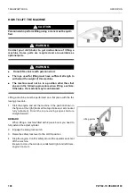
TRAVELLING POSTURE
Before starting to travel, be sure to raise and lock the outriggers,
and raise the dozer blade.
Before travelling on public roads, the work equipment should be
positioned to comply with local legal requirements for travel space
envelope.
1.
Position the upper structure so that it is facing the front of the
undercarriage (the oscillation lock cylinders can be seen) and
insert the swing lock pin.
2.
Fully extend the bucket cylinder.
3.
Either:
(a) Fully extend the first boom cylinders.
OR
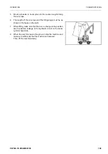
(b) Extend the first boom cylinders until the boom positioning
decals (A) are aligned correctly.
4.
Fully retract the second boom cylinders.
5.
Adjust the arm cylinder such that the front of the arm is verti-
cle.
6.
Disable the work equipment levers by switching on the control
lever lock switch.
7.
Close manual lock valves
1) For the bucket cylinder, located on the arm.
2) For the arm cylinder, located on the first boom.
After setting the machine in the travelling posture, confirm that its
overall height is below 4 m and that the distance between the
centre of the steering wheel and the front of the work equipment
is less than 3.5 m.
REMARK
This will necessitate removal of the bucket for machines fitted
with 3.0 m arm.
A
Summary of Contents for PW160-7H
Page 2: ......
Page 3: ...PW160 7H VEAM390100 3 FOREWORD ...
Page 12: ...LOCATIONS OF PLATES TABLE TO ENTER SERIAL NO AND DISTRIBUTOR FOREWORD 12 PW160 7H VEAM390100 ...
Page 18: ...18 PW160 7H VEAM390100 ...
Page 220: ...TROUBLESHOOTING OPERATION 220 PW160 7H VEAM390100 ...
Page 305: ...PW160 7H VEAM390100 305 SPECIFICATIONS ...
Page 307: ...SPECIFICATIONS SPECIFICATIONS PW160 7H VEAM390100 307 1 PIECE BOOM ...
Page 308: ...SPECIFICATIONS SPECIFICATIONS 308 PW160 7H VEAM390100 2 PIECE BOOM ...
Page 345: ......


