32
2. User Manual
Inputs
Control
Outputs
▪
CV signal from the CV interface
▪
CV Range: + 5V
Threshold Potentiometer
▪
No CV assigned: Dictates the tempo of the se-
quence
▪
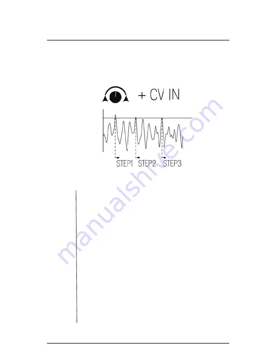
CV assigned and THRESH fully CCW: The se-
quence proceeds to the next step whenever it
receives an incoming clock or gate signal.
▪
CV assigned and THRESH not fully CCW: The
sequence proceeds to the next step whenever the
signal envelope crosses the threshold
4 Sequencer Potentiometers: Each pot sets the CV
value of the related step
▪
Output Range: +5V
When the THRESH knob itself not fully counterclockwise (CCW), it
will compare the incoming signal to the set threshold and whenever
the signal rises above the threshold, the sequence will move onto the
next step (Fig. 3).
Fig. 3


