Vers. 291020
31
19
ESC EXT
If enabled (see PRESS ESC on OTHER menu), ESC key function to reset
remote errors.
20
OK EXT
If enabled (see PRESS OK on OTHER menu), remote OK key function.
21
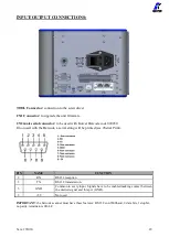
24 VDC
+24V voltage protected. The maximum current consumption is 400mA. To be used to
activate the inputs. IT CANNOT BE USED TO POWER EXTERNAL DEVICES.
22
GND
It is connected in parallel to pin 44 and to the ground connector. It is the common pin
to all inputs and outputs. The output signals must be taken between this pin (GND)
and the respective pins of the output signals. It can also be used to connect the mass
references of other devices in order to be able to pilot the various inputs in (see
schemes related to the connections for input and output).
OUTPUT 24V
23
NOT USED
24
NOT USED
25
BIT1 SEQ
Less significant weight bit to enable the Sequence (see the chart below)
26
BIT2 SEQ
27
BIT3 SEQ
More significant weight bit to enable the Sequence (see the chart below)
28
BIT1 PR
Less significant weight bit to enable Program (see the chart below)
29
BIT2 PR
30
BIT3 PR
31
BIT4 PR
32
BIT5 PR
33
BIT6 PR
More significant weight bit to enable Program (see the chart below)
34
NOT USED
35
NOT USED
36
READY
This signal is active when the screwdriver is in stand-by
37
STOP
This signal is active when the screwdriver is in STOP MOTOR
38
END SEQ
This signal is active when the pre-set sequence is correctly done.
39
END PR
This signal is active when the pre-set program is correctly done.
40
NOK
This signal works in parallel with the red light on the front panel. It advises
that at least one of the pre-set parameters have not been successful.
41
OK
This signal works in parallel with the green light on the front panel. It
advises that all the pre-set parameters have been successful.
42
MOTOR ON (/W)
It activates when the motor runs while tightening.
43
LEVER
It activates when the lever is pressed in screwing.
44
GND
It is connected in parallel to pin 22 and to the ground connector. It is the common
pin to all inputs and outputs. The output signals must be taken between this pin
(GND) and the respective pins of the output signals. It can also be used to connect
the mass references of other devices in order to be able to pilot the various inputs in
(see schemes related to the connections for input and output).
Summary of Contents for 035001
Page 50: ...Vers 291020 50 EXPLODED VIEW KDU 1 KDU 1A...
Page 52: ...Vers 291020 52 EXPLODED VIEW KDS PLxx...
Page 54: ...Vers 291020 54 EXPLODED VIEW KDS PLxxP...
Page 56: ...Vers 291020 56 EXPLODED VIEW KDS PLxxCA...
Page 58: ...Vers 291020 58 EXPLODED VIEW KDS MT1 5...


