


I.11
Switch-on and switch-off behavior
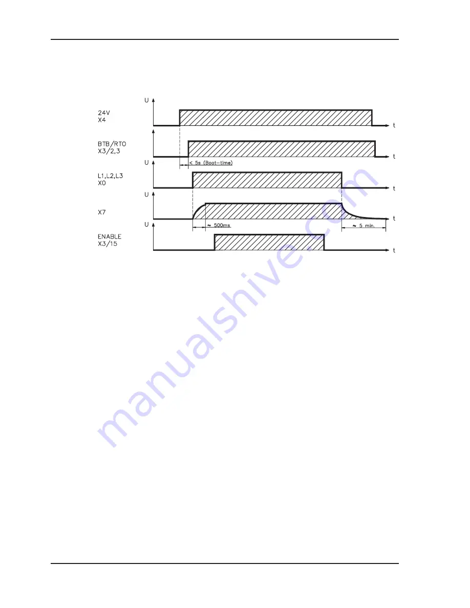
The diagram below illustrates the correct functional sequence for switching the servo amplifier on
and off.
I.11.1
Stop function to EN 60204 (VDE 0113)
If a fault occurs (
ð
p.58) the output stage of the servo amplifier is switched off and the BTB/RTO
contact is opened. In addition, a global error signal can be given out at one of the digital outputs
(terminals X3/16 and X3/17) (see online help for the setup software). These signals can be used by
the higher-level control to finish the current PLC cycle or to shut down the drive (with additional
brake or similar.).
Instruments which are equipped with a selected “Brake” function use a special sequence for
switching off the output stage (
ð
p.18).
The -AS- option can be used to switch off the drive via a positive-action (approved by the Trade
Liability Association) safety relay, so that personnel safety is ensured at the drive shaft (
ð
p.61).
The Stop functions are defined in EN 60204 (VDE 0113), Para. 9.2.2, 9.2.5.3.
There are three categories of Stop functions:
Category 0:
Shut down by immediately switching off the supply of energy to the
drive machinery (i.e an uncontrolled shut-down);
Category 1:
A controlled shut-down, during which the supply of energy to the drive
machinery is maintained to perform the shut-down, and where the energy
supply is only interrupted when the shut-down has been completed;
Category 2:
A controlled shut-down, where the supply of energy to the drive machinery
is maintained.
Every machine must be equipped with a Stop function to Category 0. Stop functions to Categories 1
and/or 2 must be provided if the safety or functional requirements of the machine make this
necessary.
You can find additional information and implementation examples in our application note “Stop and
Emergency Stop functions with SERVOSTAR 600”.
- A.4.031.3/6
20
SERVO
STAR
®
601...620 Installation Manual
General
06/02
Seidel
DC-link


