27
Electrical System
18 690 06 Rev. --
KohlerEngines.com
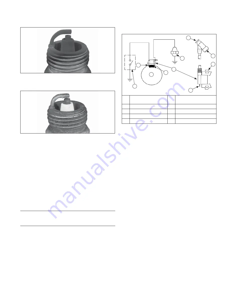
Carbon Fouled
Soft, sooty, black deposits indicate incomplete
combustion caused by a restricted air cleaner, over rich
carburetion, weak ignition, or poor compression.
Overheated
Chalky, white deposits indicate very high combustion
temperatures. This condition is usually accompanied
by excessive gap erosion. Lean carburetor settings,
an intake air leak, or incorrect spark timing are normal
causes for high combustion temperatures.
BATTERY
A 12 volt battery (not furnished) with a minimum current
rating of 230 cold cranking amps/18 amp hours should
be suf
fi
cient for cranking most electric start engine
models. Actual cold cranking requirement depends
on engine size, application and starting temperatures.
Cranking requirements increase as temperatures
decrease and battery capacity shrinks. Refer to
equipment's operating instructions for speci
fi
c battery
requirements.
If battery charge is insuf
fi
cient to turn over engine,
recharge battery.
Battery Maintenance
Regular maintenance is necessary to prolong battery
life.
Battery Test
To test battery, follow manufacturer's instructions.
ELECTRONIC IGNITION SYSTEM
Inductive Discharge Ignition System Components
A
C
D
E
F
G
H
I
J
B
A
Kill Switch/Off Position
of Switch
B
Air Gap 0.254 mm
(0.010 in.)
C
Flywheel
D
Magnet
E
Ignition Module
F
Spark Plug
G
Kill Terminal
H
Lamination
I
Spark Plug Terminal
J
Spark Plug Boot
These engines are equipped with a dependable
magneto breakerless ignition. In such a system,
electrical energy is generated by cutting of magnetic
fl
ux
lines generated from ignition magnet on engine
fl
ywheel
via prescribed air gap as it passes ignition module.
This energy is transferred through ignition module
laminations and is then converted in module electronics
and stored in module primary coil, as a current. Stored
energy is transferred at correct moment by triggering a
semiconductor switch inside module. Electrical break
by switch initiates energy transfer by causing collapse
of magnetic
fi
eld at coil primary. This includes a voltage
at coil primary that is ampli
fi
ed via transformer action at
coil secondary. Amplitude of voltage at coil secondary
is suf
fi
cient to jump gap at spark plug, igniting fuel air
mixture in gap and initiating combustion. Note that by
design, these modules only will provide proper function if
mounted in correct orientation.
This ignition system is designed to be trouble free for
life of engine. Other than periodically checking/replacing
spark plugs, no maintenance or timing adjustments
are necessary or possible. Mechanical systems do
occasionally fail or break down. Refer to Troubleshooting
to determine root of a reported problem.
Reported ignition problems are most often due to poor
connections. Before beginning test procedure, check
all external wiring. Be certain all ignition-related wires
are connected, including spark plug leads. Be certain all
terminal connections
fi
t snugly. Make sure ignition switch
is in run position.


