background image

2

TT-1675 5/16

Hazardous voltage.

Can cause severe injury or death.

Operate the generator set only when

all guards and electrical enclosures

are in place.

Moving parts.

WARNING

Short circuits. Hazardous voltage/current can cause

severe injury or death.

Short circuits can cause bodily injury

and/or equipment damage

.

Do not contact electrical

connections with tools or jewelry while making adjustments or

repairs. Remove all jewelry before servicing the equipment.

Installation Procedure

See Figure 16 for the installed kit illustrations. Refer to

the generator set operation or service manual for items

not shown.

Note:

Apply pipe sealant to the male threads of all pipe

fittings before installation.

1.

Remove the generator set from service.

1.1 Press the generator set master control

OFF/RESET button.

1.2 Disconnect the power to the battery charger, if

equipped.

1.3 Disconnect the generator set engine starting

battery, the negative (--) lead first.

Note:

Before installing the sound shield,

disconnect and route the battery leads

through the holes provided in the skid.

1.4 Remove the junction box panel(s) as needed to

access the wiring.

1.5 Remove the four controller panel screws.

Note:

Clearly mark all disconnected leads from

the controller with tape to simplify

reconnection.

1.6 Disconnect the following controller connectors.

See the corresponding wiring diagram found in the

operation manual for more details on wiring.

D

P1 (35-pin) connector

D

P2 (14-pin) connector

D

P3 (8-pin) connector

D

P4 Ethernet connector

D

Any other external leads to the controller.

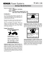
1. P3 (8-pin) connector

2. P2 (14-pin) connector

3. P1 (35-pin) connector

4. P4 Ethernet connector

1

2

3

4

GM89493-

Figure 1

Decision-Maker

3500 Controller

Connectors

Summary of Contents for GM93516-KP1

Page 1: ...set as follows 1 Press the generator set off reset button to shut down the generator set 2 Disconnect the power to the battery charger if equipped 3 Remove the battery cables negative lead first Reconnect the negative lead last when reconnecting the battery Follow these precautions to prevent the starting of the generator set by the remote start stop switch Risk of fire Can cause severe injury or ...

Page 2: ...e generator set master control OFF RESET button 1 2 Disconnect the power to the battery charger if equipped 1 3 Disconnect the generator set engine starting battery the negative lead first Note Before installing the sound shield disconnect and route the battery leads through the holes provided in the skid 1 4 Remove the junction box panel s as needed to access the wiring 1 5 Remove the four contro...

Page 3: ...d the cover 1 1 End bracket cover Figure 2 End Bracket Cover 1 10 Remove the belt guard by removing the belt guard brackets and hardware 2 Construct the framework GM93516 B 1 Rails GM94934 qty 4 2 Internal rails GM94937 qty 6 Mounting brackets GM86091 qty 6 bolts X 6224 20 qty 12 and nuts X 6210 7 qty 12 on the top of each rail See Figure 12 3 Extrusion mounting brackets GM85876 qty 6 See Figure 5...

Page 4: ...d RH bulkheads GM93569 and GM93568 as shown in Figure 6 Secure the bottom of the bulkheads to the existing skid using a screw M933 06020 60 washer X 25 40 and nut M6923 06 80 for each bulkhead Secure the sidesofthe LHand RHbulkheadstothe two internal rails using a bolt X 6224 20 washer X 25 37 and nut X 6210 7 for each bulkhead 2 5 Positiontheupperbulkhead GM93567 asshown in Figure 6 Secure the bo...

Page 5: ...her GM96474 and cap GM55130 over each protruding stud 3 5 Attach the hose GM95105 and the hose clamp 274976 to the air cleaner inlet 4 Connect the fuel lines 4 1 Connect the fuel inlet line GM95059 to the fuel inlet on the engine 4 2 Remove the fuel fitting and O ring from the fuel return connection point nonservice side of the unit Assemble fitting GM39538 to the fuel return on the engine 4 3 Con...

Page 6: ... 2 See Figure 12 for bracket location 3 Rail GM94935 qty 2 4 Corner GM86035 qty 4 and screw X 67 141 qty 24 5 Foam GM87548 or GM88911 qty 2 1 4 1 2 5 Figure 11 Top Rail and Bracket Installation 7 1 Position the internal rails GM94936 qty 2 as shown in Figure 11 On each end of the internal rail secure a mounting bracket GM86091 using four bolts X 6224 20 and four nuts X 6210 7 per bracket See Figur...

Page 7: ...6091 qty 2 bolts X 6224 20 qty 4 and nuts X 6210 7 qty 4 3 Brackets GM86091 qty 2 bolts X 6224 20 qty 8 and nuts X 6210 7 qty 8 4 Bracket GM86091 bolts X 6224 20 qty 4 and nuts X 6210 7 qty 4 5 Wing nuts X 276 9 qty 2 installed when installing engine roof 6 Wing nuts X 276 9 qty 2 installed when installing alternator roof 7 Wing nuts X 276 9 qty 2 installed when installing controller panel 8 Wing ...

Page 8: ...ator roof GM93544 or GM95449 2 Engine roofs qty 2 GM93543 or GM95448 2 2 Figure 14 Roofs 9 1 Position the alternator roof GM93544 or GM95449 and engine roofs qty 2 GM93543 or GM95448 onto the sound enclosure as shown in Figure 14 Attach the alternator roof to the mounting brackets in the top rail and secure using two wing nuts X 276 9 See Figure 12 for more detail Attach the engine roofs to the mo...

Page 9: ...item 4 two places 10 5 Align the pins with the holes in the base and install the front panel GM93536 or GM95441 on the engine end of the unit See Figure 15 item 5 10 6 Align the pins with the holes in the base and install the two RH panels GM93535 or GM95440 to the service side engine end ofthe unit See Figure 15 item 6 two places 10 7 Align the pins with the holes in the base and install the RH a...

Page 10: ...ator panel GM93539 or GM95444 3 Exhaust panel GM93538 or GM95443 4 LH panel GM93537 or GM95442 5 Front panel GM93536 or GM95441 6 RH panel GM93535 or GM95440 7 RH alternator panel GM93541 or GM95446 8 Controller panel GM93542 or GM95447 6 2 7 8 6 4 Figure 15 Panel Identification ...

Page 11: ...20 20 qty 12 5 Alternator panel RH GM93541 or GM95446 6 Panel RH GM93535 or GM95440 qty 2 7 Front panel GM93536 or GM95441 8 Panel LH GM93537 or GM95442 qty 2 9 Exhaust panel GM93538 or GM95443 10 Alternator panel LH GM93539 or GM95444 11 Bulkhead connection panel GM93545 or GM95450 12 Rear Panel GM93540 or GM95445 GM93516 B 9 8 12 7 11 1 5 6 2 3 4 10 3 6 8 Figure 16 Sound Shield ...

Page 12: ...33 in GM94933 4 Rail sound shield 41 3 in GM94934 2 Rail sound shield 96 5 in GM94935 2 Rail internal sound shield 33 in GM94936 6 Rail internal sound shield 41 3 in GM94937 1 Fuel line flex supply 85 in GM95059 1 Fuel line flex return 100 in GM95060 Qty Description Part Number 2 Nut hex 6 mm M6923 06 80 1 Nut hex 10 mm M6923 10 80 4 Screw hex cap M6 x 12 mm M933 06012 60 2 Screw hex cap M6 x 20 m...

Page 13: ...445 1 Panel alternator RH 42 1 x 13 3 in GM95446 1 Panel controller 42 1 x 13 3 in GM95447 2 Roof engine 35 6 x 34 8 in GM95448 1 Roof alternator 26 8 x 34 8 in GM95449 1 Panel bulkhead connection 6 3 x 34 7 in GM95450 Qty Description Part Number 2 Nut hex 6 mm M6923 06 80 1 Nut hex 10 mm M6923 10 80 4 Screw hex cap M6 x 12 mm M933 06012 60 2 Screw hex cap M6 x 20 mm M933 06020 60 1 Screw hex cap ...

Page 14: ...14 TT 1675 5 16 Notes ...

Page 15: ...15 TT 1675 5 16 Notes ...

Page 16: ...er Systems Asia Pacific Headquarters 7 Jurong Pier Road Singapore 619159 Phone 65 6264 6422 Fax 65 6264 6455 Availability is subject to change without notice Kohler Co reserves the right to change the design or specifications without notice and without any obligation or liability whatsoever Contact your local Kohlerr generator set distributor for availability 2016 by Kohler Co All rights reserved ...

Reviews: