


TT-1303
7/02
9
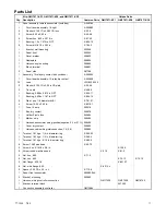
Description
Controller
Connection
Kit Terminal
14-Relay Dry
Contact Kit
Terminal
(Relay Signal)
14-Relay Dry
Contact Kit
Terminal
(Relay Contacts)
Remote Annunciator
Terminal (factory wire
designations)
Battery (+)
42A
42A Input
—
—
Ground/Battery (--)
2
2 Input
—
—
Battery (+)
—
P (from battery)
42B
42B
Ground/Battery (--)
—
N (from battery)
K1, C terminal
N
Overspeed
RDO1
K1 Input
K1, NO terminal
39
Overcrank
RDO2
K2 Input
K2, NO terminal
12
High Engine Temperature Shutdown
RDO3
K3 Input
K3, NO terminal
36
Low Oil Pressure Shutdown
RDO4
K4 Input
K4, NO terminal
38
Overvoltage (Aux.)
RDO20
K5 Input
K5, NO terminal
26
System Ready
RDO17
K6 Input
K6, NO terminal
60
Master Switch Not in Auto
RDO9
K7 Input
K7, NO terminal
80
Low Oil Pressure Warning
RDO7
K8 Input
K8, NO terminal
41
Emergency Stop
RDO14
K9 Input
K9, NO terminal
48
Battery Charger Fault
RDO11
K10 Input
K10, NO terminal
61
Low Battery Voltage (Aux.)
RDO12
K11 Input
K11, NO terminal
62
Low Fuel (Level or Pressure)
RDO8
K12 Input
K12, NO terminal
63
Low Water Temperature
RDO5
K13 Input
K13, NO terminal
35
High Engine Temperature Warning
RDO6
K14 Input
K14, NO terminal
40
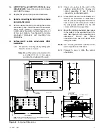
Figure 10
Remote Annunciator Kit Wiring Connections
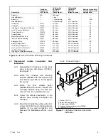
6.3
Flush-mount
remote
annunciator
final
installation.
6.3.1
Reassemble the front panel to the back
panel using two drill screws (X-794-2).
See Figure 11.
6.3.2
Attach
the
L-shaped
side
mounting
brackets (293993) to the back panel using
four drill screws (X-794-2). Do not tighten
the screws.
6.3.3
Attach
the
front
adapter
panel
(293992-BLK) studs to the L-shaped side
mounting brackets using four 6-32 hex
nuts (X-71-2). Do not tighten the nuts.
6.3.4
Center the remote annunciator in the
adapter panel opening and tighten the
hardware.
6.3.5
Mount the kit inside the pull box using four
screws (X-50-72). Use mounting hardware
suitable for the wall composition and
thickness for installations without a pull
box.
6.3.6
Proceed to step 7.
TT1023
1. Nut, hex (X-71-2)
2. Screw, pan head (X-50-72)
3. Adapter panel (293992)
4. L-shaped side mounting bracket (293993)
5. Drill screw (X-794-2)
1
2
3
4
5
Figure 11
Flush-Mount Remote Annunciator
Installation


