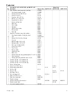
Kohler GM17071-KP1 Installation Instructions Manual Download Page 12

12

TT-1303

7/02

Parts List

Qty.

Kits: GM17071-KP1S, GM17071-KP2S, and GM17071-KP3S

Unique Parts

Qty.

Description

Common Parts GM17071-KP1S GM17071-KP2S GM17071-KP3S

1

Panel assembly, remote annunciator (includes:)

A-258782-SD

1

Circuit board assembly, 16-light

A-292885

2

Washer, 0.146 ID x 0.285 OD lock

X-22-6

2

Screw, 6-32 x 0.50 in.

X-49-26

4

Screw, hex, 8-32 x 0.375 in.

X-67-43

1

Bushing, 1.0 x 1.375 in. NPT

X-634-15

6

Screw, drill, 8-18 x 0.50 in.

X-794-2

1

Bracket, wall mounting

253346

1

Panel, front

253350

1

Decal, marker

258832

1

Nameplate

258834

1

Harness, engine wiring

258890

1

Block, terminal

258891

2

Panel, side

287798

1

Assembly, 14-relay dry contact box (includes:)

A-293983

1

Circuit board assembly, 14-relay dry contact

A-320639

13

Lead

LW-1803-0000

2

Washer, 0.125 ID x 0.25 in OD plain

X-25-46

2

Tie, cable

X-468-5

1

Bushing, 0.688 x 0.875 in. NPT

X-634-11

1

Bushing, 0.938 x 1.187 in. NPT

X-634-14

2

Rivet, pop, 1/8 diameter Al/Al

X-781-21

4

Screw, 10-24 x 0.50 in.

X-6216-1

1

Fuse, 10-amp

223316

1

Box, dry contact

226676

1

Holder, 2-pole fuse

343694

1

Marker, strip

256494

1

Harness, annunciator wiring (positive/negative, 3.4 m (11 ft.) 256495

1

Cover, dry contact

256880

1

Harness, cable wiring interconnection, 1.5 (5 ft.)

293982

1

Terminal, 16-14 ga., 1/2 in. diameter ring

X-283-32

1

Terminal, 16-14 ga., 1/4 in. diameter ring

X-283-4

1

Terminal, 16-14 ga., 5/16 in. diameter ring

X-283-5

4

Screw, 10-32 pan head

X-50-72

2

Screw, hex, 5/16-18 x 3/4 in.

X-125-3

6

Screw, round machine head

X-51-3

X-51-3

4

Nut, hex, 6-32

X-71-2

6

Nut, hex, 8-32

X-70-12

X-70-12

2

Nut, flange, 5/16-18

X-6210-7

6

Nut, whiz flange, 8-32

X-6210-4

6

Spacer, 0.25 OD x 0.5 in. L

X-712-9

1

Panel, front annunciator

293992-SD

2

Bracket, mounting

293993

1

Harness, wiring controller connection

GM17033

GM17029

GM16753

1

Bracket, terminal block

347292

1

Connection assembly, controller

GM13984

Summary of Contents for GM17071-KP1

Page 1: ...stations Read the entire installation procedure and compare the kit parts with the parts list in this publication before beginning installation Perform the steps in the order shown Observe applicable...

Page 2: ...temperature shuts down the generator set Line Power The lamp illuminates when commercial utility power or other source supplies the power when equipped with an auxiliary contact When the lamp illumina...

Page 3: ...pped 1 3 Disconnect the generator set engine starting battery ies negative lead first 2 Mount and connect the controller connection assembly 2 1 GM17070 KP1 and GM17070 KP1S kits 20 300 kW 2 1 1 Remov...

Page 4: ...access door 2 3 3 Attach the controller connection assembly GM13984 to the junction box inner panel studs using six spacers X 712 9 and nuts X 70 12 Place the spacers between the controller connection...

Page 5: ...location D An area as near to the generator set controller as practical 3 2 Remove the four cover screws X 6216 1 and lift the box cover 256880 to access the internal components 3 3 Mount the 14 relay...

Page 6: ...5 16 in diameter or X 283 32 1 2 in diameter as required Do not use terminals 42A and 2 on the 14 relay dry contact box terminal strip to supply voltage to the relay contacts The user must attach sep...

Page 7: ...ctrical box in the wall See Figure 8 for the mounting hole dimensions Protect the remote annunciator from dust and debris when drilling the holes Note Use mounting hardware suitable for the wall compo...

Page 8: ...total wire length for each conductor is 122 m 400 ft According to the chart in Figure 9 this example requires 14 gauge wire for leads N and 42B only Use stranded or solid 18 or 20 gauge wire for signa...

Page 9: ...Pressure RDO8 K12 Input K12 NO terminal 63 Low Water Temperature RDO5 K13 Input K13 NO terminal 35 High Engine Temperature Warning RDO6 K14 Input K14 NO terminal 40 Figure 10 Remote Annunciator Kit W...

Page 10: ...Move the remote annunciator alarm horn switch to SILENCE to stop the alarm horn The respective remote annunciator lamp remains lit 8 3 Disconnect the generator set from the system load with the line c...

Page 11: ...ing 0 688 x 0 875 in NPT X 634 11 1 Bushing 0 938 x 1 187 in NPT X 634 14 2 Rivet pop 1 8 diameter Al Al X 781 21 4 Screw 10 24 x 0 50 in X 6216 1 1 Fuse 10 amp 223316 1 Box dry contact 226676 1 Holde...

Page 12: ...1 Bushing 0 688 x 0 875 in NPT X 634 11 1 Bushing 0 938 x 1 187 in NPT X 634 14 2 Rivet pop 1 8 diameter Al Al X 781 21 4 Screw 10 24 x 0 50 in X 6216 1 1 Fuse 10 amp 223316 1 Box dry contact 226676...

Reviews: