TT-1601 5/16
5
3.
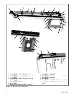
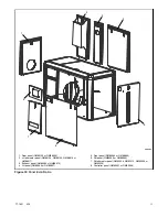
Attach the foam and seal on bulkhead.
D
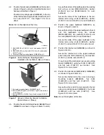
Attach the foam and seal to the bulkhead as shown
in Figure 8 for standard sound shield kits or
Figure 9 for UMS sound shield kits.
GM86016-A
1. Foam (GM87548 qty. 2)
2. Foam (GM86092-12)
3. Foam (GM86092-14)
4. Foam (GM86092-15)
5. Seal (X-6422-12)
6. Foam (GM86092-13)
1
2
3
4
5
6
Figure 8
Foam and Seal Installation for Standard
Sound Shield Kits GM86016-KP1/-KP3/
-KP4
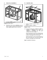
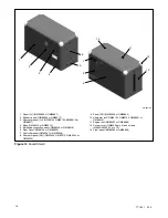
Follow the below method to attach the foam
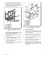
pieces for UMS sound shield kits:
3.1 Apply adhesive (GM96475) to the foam pieces
shown in Figure 9.
3.2 Stick the insulating hanger stud (GM96473) onto
the adhesive at equal distances.
3.3 Install the foam piece and allows the stud to
protrude through foam piece.
3.4 Install a washer (GM96474) and cap (GM55130)
over the protruding stud.
GM88267-C
1. Foam (GM88911 qty. 2)
2. Foam (GM88906-17)
3. Foam (GM88906-22)
4. Foam (GM88906-19)
5. Foam (GM88906-20)
6. Foam (GM88906-18)
7. Foam (GM88906-21)
8. Seal (X-6422-12)
1
2
3
4
5
6
7
8
Figure 9
Foam and Seal Installation for UMS Sound
Shield Kits GM88267-KP1/-KP2/-KP3
4.
Connect the fuel lines.
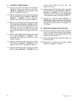
4.1 Connect the fuel-inlet line (GM86395) to the fuel
inlet on the engine. See Figure 11 and Figure 12
for connection location.
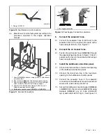
4.2 Remove the fuel fitting from the fuel-return
connection point (nonservice side of the unit).
4.3 Connect the straight union fitting (X-695-2) to the
fuel-return connection point.
4.4 Connect the fuel-return line (GM86395) to the
straight union fitting installed in step 4.3.
4.5 Secure the fuel return line to the left side of the
engine using a hose clamp (X-672-32) and
existing hardware and torque to 15 Nm (11 ft. lbs).
See Figure 10.
Summary of Contents for 40EFOZDJ
Page 15: ...TT 1601 5 16 15 Notes ...


