background image

5-2

A-61602  February 2009 

Problem

Possible Solution

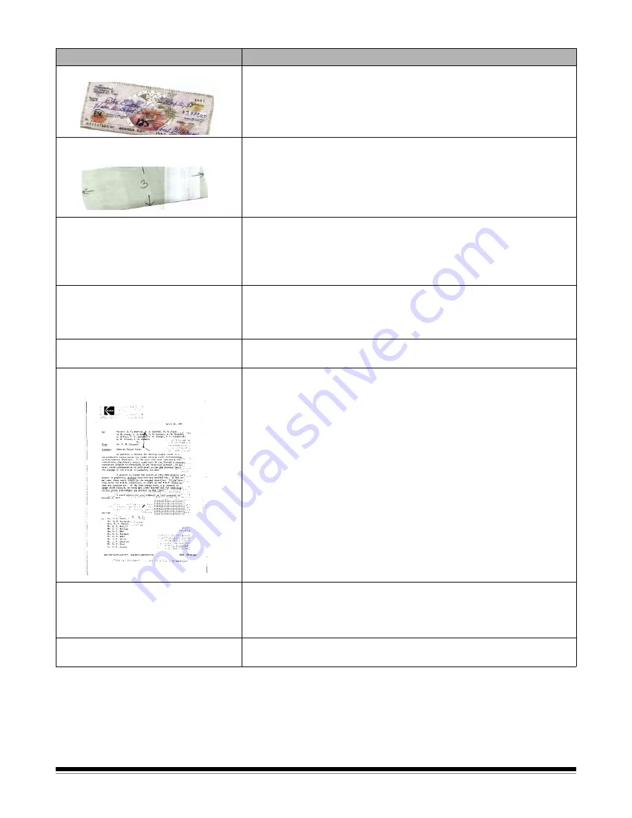
Image has clipped corners

If your images have clipped corners, the skew angle was too large for the 
scanner to handle. Be sure documents are placed in the input tray with 
the edges aligned and the side guides positioned correctly to 
accommodate the size documents you are feeding to avoid large skew 
angles.

First image in a batch appears “washed 
out”

If the scanned documents in a batch have more than a 25 degree skew, 
the first image in the batch may appear washed out. Be sure that 
documents are placed in the input tray with the edges aligned and the 
side guides positioned correctly to accommodate the size documents 
you are feeding to avoid large skew angles.

Image appears to be cut off

If you are scanning a document with a reflective area (such as a 
hologram), and this reflective area is fed “face up” and off-center such 
that it passes over the left-edge sensor, the sensor will be triggered as if 
it were the end of the page and will result in a cut-off image. 

• Rescan the document by feeding it face down.

Images are not cropped correctly

• If 

auto 

or

 aggressive cropping

 is enabled, and your images are not 

cropped correctly, clean the white background strips in the calibration 
area. See the procedures in Chapter 4, 

Maintenance

 “Cleaning the 

calibration area”. 

Roller marks appear on the document 
after scanning

Clean the rollers. See the procedures in Chapter 4, 

Maintenance

.

Images have black background bleed- 
through

When scanning translucent documents, black bleed-through may be 
displayed on the image. To minimize this, adjust the 

Contrast

 value or 

select 

Fixed Processing

 to improve the image. For more information on 

Contrast and Fixed Processing, see the 

Image Processing Guide

 on the 

Installation CD.

Scanner is running slow

• Your PC may not meet the minimum requirements for the scanner.
• The scanner is rated and designed to operate with USB 2.0, but will 

function with USB 1.1. If you are using a USB 1.1 connection, update 
your connection to USB 2.0.

Cannot scan after Standby or Hibernate 
with Microsoft Windows Vista

Upgrade to Service Pack 1 or higher.

Summary of Contents for I1120 - Document Scanner

Page 1: ......

Page 2: ...the disposal of consumable items that are replaced during maintenance or service follow local regulations or contact Kodak locally for more information The Kodak ScanMate i1120 Scanner contains lead i...

Page 3: ...mission Maschinenl rminformationsverordnung 3 GSGV Der arbeitsplatzbezogene Emissionswert betr gt 70 dB A Machine Noise Information Ordinance 3 GSGV The operator position noise emission value is 70 dB...

Page 4: ...OVERVIEW 1 1 INSTALLATION 2 1 SCANNING 3 1 MAINTENANCE 4 1 TROUBLESHOOTING 5 1 APPENDICES...

Page 5: ...he scanner Image Processing Guide explains how to use basic image processing features and is provided on the Installation CD in PDF format Smart Touch User s Guide provides information and procedures...

Page 6: ...ill also display error codes See Chapter 5 Troubleshooting for a listing of these error codes Scroll button allows you to select or scroll through predefined functions 1 through 9 Start button launche...

Page 7: ...rt connects the scanner to the PC Inside view Calibration guide for optimum image quality keep the calibration guide clean Pre separation pad and rollers provides smooth document feeding and separatio...

Page 8: ...uide skip this section The Kodak Driver Software must be performed first before installing any other portions of the scanner Installing the Kodak Driver Software 1 Insert the Kodak ScanMate i1120 Scan...

Page 9: ...nt The installation will start and several progress screens will be displayed 5 Click Finish when the installation is complete 6 Remove the Kodak ScanMate i1120 Scanner Installation CD from the CD ROM...

Page 10: ...A 61602 February 2009 2 3 3 Align the four tabs on the input tray with the slots on the scanner 4 Roll the input tray toward the back of the scanner until it snaps into place 5 Close the scanner cover...

Page 11: ...Attaching the output tray 1 Locate the output tray slots on the scanner 2 Align the output tray pins with the slots and lower the output tray into place NOTE The output tray can be folded up when not...

Page 12: ...packed with your scanner 2 Attach the power cord for your power type to the power supply NOTE Be sure that the power cord is securely attached to the power supply 3 Plug the output power cord from the...

Page 13: ...ts Please wait while the operating system synchronizes the scanner with the installed software When the installation process is complete and ready to scan the green LED indicator light will stop flash...

Page 14: ...canning with Smart Touch 3 4 Getting your scanner ready to scan 1 Be sure the scanner is on and ready to scan green indicator light is on and constant 2 Adjust the side guides by sliding them in or ou...

Page 15: ...nts into the scanner one at a time 2 Remove all staples and paper clips before scanning Staples and paper clips on documents may damage the scanner and documents 3 All inks and correction fluids on th...

Page 16: ...find use and share PaperPort provides a unique visual desktop that displays thumbnails of your documents so you can easily browse and locate information fast ScanSoft OmniPage this productivity appli...

Page 17: ...information on how to use Smart Touch see the User s Guide for Smart Touch provided on the Installation CD 1 Press the Scroll button until number 6 is displayed in the function window 2 Press the Sta...

Page 18: ...eed easily if several documents feed at the same time or if streaks appear on your images it is time to clean your scanner The section entitled Supplies and consumables at the end of this chapter prov...

Page 19: ...oap and water after performing maintenance procedures Refer to the MSDS for more information NOTE For easier cleaning you can remove the roller See Replacing the feed roller assembly later in this cha...

Page 20: ...er cover 2 Squeeze the plastic clamps that hold the pre separation pad in place and lift it out of position 3 Wipe the pre separation pad from top to bottom with a roller cleaning pad 4 Reinsert the p...

Page 21: ...pe the front and rear calibration guides again with an almost dry Staticide wipe to remove any streaks IMPORTANT When cleaning the front calibration area be careful not to bend the white tabs bending...

Page 22: ...he scanner cover 2 Squeeze the plastic clamps that hold the pre separation pad in place and lift it out of position 3 Insert the new pre separation pad into position aligning it with the slots and pus...

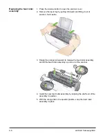
Page 23: ...rward and lifting it out of position Set it aside 3 Rotate the orange tab upward to release the feed roller assembly and lift the feed roller assembly up and out of the scanner 4 Install the new feed...

Page 24: ...oward the back of the scanner until it snaps into place Supplies and consumables Contact your scanner supplier to order supplies NOTE Items and catalog numbers are subject to change Description CAT No...

Page 25: ...for the width and length of the documents you are scanning all documents meet the specifications for size weight and type See Appendix A Specifications for more information the scanner is clean the pr...

Page 26: ...it were the end of the page and will result in a cut off image Rescan the document by feeding it face down Images are not cropped correctly If auto or aggressive cropping is enabled and your images ar...

Page 27: ...blem The scanner model and serial number Computer configuration Software application you are using Code Problem Remedy E 1 E 2 E 3 E 4 Scanner failure Turn the scanner off then on again restart the sc...

Page 28: ...86 36 cm 8 5 x 34 in Minimum document size 6 35 x 5 cm 2 5 x 2 in ADF Capacity 50 sheets Recommended Daily Volume 500 Illumination Fluorescent Electrical requirements 100 240 V international 50 60 Hz...

Page 29: ...ong up to 400 dpi 3 2 GHz Intel Pentium IV processor with 1 GB of RAM For longer documents higher resolutions 3 2 GHz Intel Pentium IV processor with 3 GB of RAM USB port 2 0 compatible with USB 1 1 b...

Page 30: ...mponent including breakage of a connector cover glass pins or seal c from service modification or repair not performed by Kodak or a service provider authorized by Kodak or by tampering use of counter...

Page 31: ...s seeking services for Kodak Scanners covered under this Limited Warranty must obtain a Return Material Authorization number RMA by calling 800 822 1414 and within ten 10 business days from the date o...

Page 32: ...he box to ensure proper receipt and credit of the defective product Depot service If the Kodak Scanner is not eligible for Advance Exchange or On Site Service an eligible purchaser may utilize our Dep...

Page 33: ...Kodak Scanners www Kodak com go docimaging For U S Service Repair and Technical Assistance by Telephone 5 a m to 5 p m Monday Friday 800 822 1414 excluding Kodak holidays For Technical Documentation...

Page 34: ......

Reviews: