background image


WALL MOUNT INSTALLATION 

For Model No.: RA3830SQB-WM-5 and RA3836SQB-WM-5 


Preparation before Installation 


NOTE: 

TO  AVOID  DAMAGE  TO  YOUR  HOOD, 
PREVENT DEBRIS FROM ENTERING THE   
VENT OPENING. 

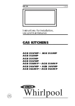
Decide  the  location  of  the  venting  pipe  from  the 
hood to the outside. Refer to Figure 8. 

A straight, short venting run will allow the hood to 
perform more efficiently. 

Try to avoid as many transitions, elbows, and long 
run as possible.  This may reduce the performance 
of the hood. 

Temporarily  wire  the  hood  to  test  for  proper 
operation before installing.  If  the  hood  does  not  
operate,  check  the  circuit breaker  or  house  fuse.  
If  the  hood  is  still  not  working, disconnect  power  
supply    and    check    the    continuity    of    all    wire 
connections. 

Peel protective film off the hood (if any).  

Use  duct  tape  to  seal  the  joints  between  pipe 
sections. 

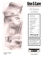
If  necessary,  prepare  back  wall  frame  with  cross 
framing  lumber  for  secure  installation.    Using 
references on Table 2 and measurements on page 
14-15,  decide  the  level  of  the  lumber.    Refer  to 
Figure 9. 


Hood Installation 


CAUTION: USE HAND TOOLS ONLY.  DO NOT 

OVER TIGHTEN SCREWS. IT MAY CAUSE DAMAGE 
TO THE HOOD. 

CAUTION:  If  moving  the  cooking  range  is 

necessary to install the hood, turn off the power in 
an electric range at the main electrical box. SHUT 
OFF  THE  GAS  BEFORE  MOVING  A  GAS  RANGE.  
And use a protective covering to protect cooktop 
and/or countertop from damage.
 
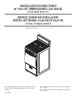
1.  Using  references  on  Table  2  and  measurements 

on page 14-15, mark the leveling point of the hood.  
Position  mounting  screws  (provided)  on  the  wall, 
leaving 1/8” away from the wall as shown in Figure 
10. 

2.  Optional step for adjusting hood-mounting bracket 

height: 

Loosen hood-mounting brackets at the back of 
the  hood,  adjust  brackets  and  tighten  screws 
as shown in Figure 11. 

3.  Align Hood-Mounting Bracket to the two screws on 

the wall and hook hood into place.  Tighten screws 
to secure hood to the wall. 

CAUTION: MAKE SURE THE HOOD IS SECURE 

BEFORE RELEASING. 

Figure 8 


Figure 9 


Figure 10 


Figure 11 


Mounting Screws 

Summary of Contents for RA3830SQB-5

Page 1: ...KOBE Range Hoods Deluxe Series RA38 SQB 5 Series Model No Under Cabinet RA3830SQB 5 30 RA3836SQB 5 36 Wall Mount RA3830SQB WM 5 30 RA3836SQB WM 5 36 INSTALLATION INSTRUCTIONS AND OPERATION MANUAL...

Page 2: ...T INSTALL THE UNIT AND KEEP ALL ORIGINAL PACKAGING MATERIAL 2 Have your original invoice as proof of purchase and product serial number ready 3 Contact your merchant for product replacement due to shi...

Page 3: ...E 12 SPECIFICATIONS 13 MEASUREMENTS DIAGRAMS 14 PARTS LIST 16 CIRCUIT DIAGRAM 18 TROUBLE SHOOTING 19 WARRANTY 20 WARRANTY INFORMATION FORM 22 READ ALL INSTRUCTIONS CAREFULLY BEFORE STARTING A L L W I...

Page 4: ...atment negligence or any other circumstances beyond the control of KOBE RANGE HOODS authorized agents Any repair carried out without the supervision of KOBE RANGE HOODS authorized agents will automati...

Page 5: ...ou still smell gas call the Gas Company and Fire Department right away CAUTION 1 For general ventilation use only Do not use to exhaust hazardous or explosive materials and vapors 2 To reduce the risk...

Page 6: ...e Hood B Warranty Registration Card C Quick Reference Guide D Baffle Filter x 2 30 hood x 3 36 hood E 6 Round Plastic Collar F Wire Cap x 3 G Screws Package A B C D Knob is attached to baffle filter E...

Page 7: ...ide D Baffle Filter x 2 30 hood x 3 36 hood E 6 Round Plastic Collar F Duct cover Mounting Bracket G Adjustable Duct Cover H Screws Package I Wire Cap x 3 J Screws Package A B C D Knob is attached to...

Page 8: ...ing B Height of Floor to Counter Top Standard 36 C Preferred Height of Counter Top to Hood Bottom Minimum 26 to 30 D Height of Hood E Height of the Cabinet FOR WALL MOUNT WITH OPTIONAL DUCT COVER TABL...

Page 9: ...SHARP EDGES PLEASE WEAR PROTECTIVE GLOVES IF REMOVING ANY PARTS FOR INSTALLING CLEANING OR SERVICING NOTE BE CAREFUL WHEN USING ELECTRICAL SCREWDRIVER DAMAGE TO THE HOOD MAY OCCUR Installation Conten...

Page 10: ...e and create access opening for electrical wires and exhaust under the cabinet Hood Installation CAUTION USE HAND TOOLS ONLY DO NOT OVER TIGHTEN SCREWS IT MAY CAUSE DAMAGE TO THE HOOD CAUTION If movin...

Page 11: ...CAL CODES BEFORE CONNECTING WIRES SWITCH POWER OFF AT SERVICE PANEL AND LOCK SERVICE PANEL TO PREVENT POWER FROM BEING SWITCHED ON ACCIDENTALLY If hood is operating normally connect three wires black...

Page 12: ...allation Using references on Table 2 and measurements on page 14 15 decide the level of the lumber Refer to Figure 9 Hood Installation CAUTION USE HAND TOOLS ONLY DO NOT OVER TIGHTEN SCREWS IT MAY CAU...

Page 13: ...the position of the Duct Cover Mounting Bracket F Use reference E from Table 2 and measurements on page 14 15 Attach and secure Duct Cover Mounting Bracket F with two screws provided Refer to Figure...

Page 14: ...r cooking and keep fans running while cooking Adjust speed as needed To operate the fan function Press button to choose from speed o Q QuietMode speed o L Low speed o H High speed Press OFF to turn fa...

Page 15: ...orn spots Use dry soft towel to dry the hood 3 DO NOT allow deposits to accumulate or remain on the hood 4 DO NOT use ordinary steel wool or steel brushes Small bits of steel may adhere to the surface...

Page 16: ...9 3 4 x 20 1 2 x 12 5 8 RA3836SQB 5 and RA3836SQB WM 5 35 3 4 x 20 1 2 x 12 5 8 OPTIONAL ACCESSORIES W x D x H 1 30 Stainless Steel Back Panel SSP30 30 x 1 10 x 32 2 36 Stainless Steel Back Panel SSP3...

Page 17: ...measurements are converted from millimeters Inch measurements are estimated All measurements in are millimeters FOR UNDER THE CABINET MODEL NO RA3830SQB 5 30 RA3836SQB 5 36 FOR WALL MOUNT MODEL NO RA...

Page 18: ...15 Hood Mounting Bracket Duct Cover Mounting Bracket...

Page 19: ...0401 0120 04 Capacitor x 1 RA3836SQB 5 L1 0401 0120 24 3 LED Light Driver L1 0402 D001 4 Capacitor Box L1 0524 0003 5 LED Light 3W x 2 L1 0403 0301 6 Control Panel Bracket L1 0207 3830 7 Control Switc...

Page 20: ...apacitor x 1 RA3830SQB WM 5 L1 0401 0120 04 Capacitor x 1 RA3836SQB WM 5 L1 0401 0120 24 5 LED Light Driver L1 0402 D001 6 Capacitor Box L1 0524 0003 7 LED Light 3W x 2 L1 0403 0301 8 Control Panel Br...

Page 21: ...18 CIRCUIT DIAGRAM MODEL NO RA3830SQB 5 30 RA3836SQB 5 36 RA3830SQB WM 5 30 RA3836SQB WM 5 36...

Page 22: ...tive Replace LED light fixture s The light wiring s is loose Check wire continuity from Control Panel to LED Driver to LED light fixture s The control panel or LED light driver is defective Replace th...

Page 23: ...ed States and Canada It is non transferable and applies only to the original purchaser and does not extend to subsequent owner of this product In Hawaii Alaska and Canada this warranty is limited Ther...

Page 24: ...ervice you will be responsible for all expenses associated with the requested service including parts labor shipping travelling and any other expense related to the service request TO REQUEST WARRANTY...

Page 25: ...1 Date of purchase 2 Model No 3 Serial No For warranty service or spare parts purchase contact KOBE Service Center USA ONLY Toll Free 1 877 BUY KOBE 289 5623 Email customer service koberangehoods com...

Page 26: ...s recommand d utiliser cette hotte l tranger puisque l alimentation lectrique pourrait ne pas tre compatible et enfreindre le code de l lectricit de ce pays L usage de la hotte KOBE l tranger est votr...

Reviews: