Technical Manual
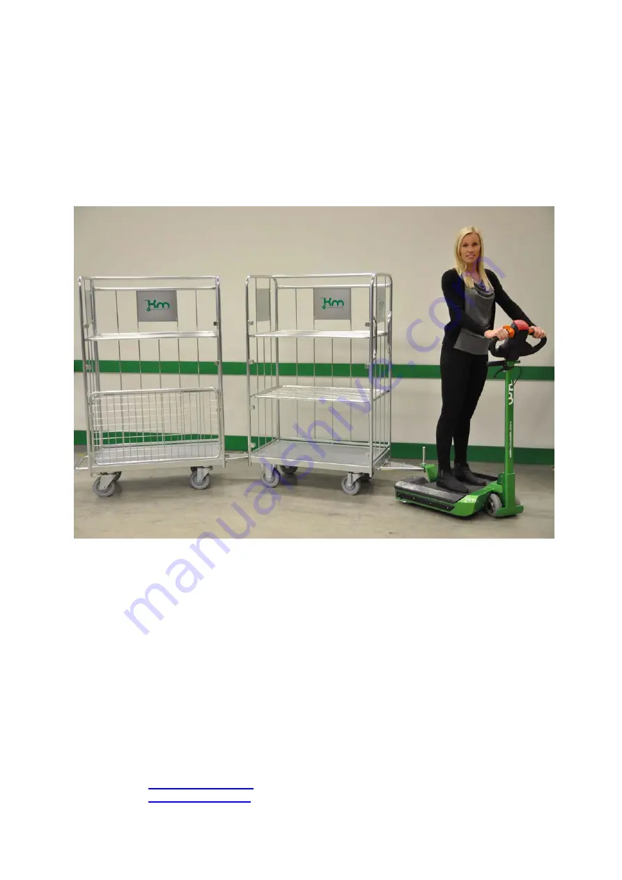
360-drive
Konga Mekaniska Verkstad AB Dång 2 SE 362 93 TINGSRYD Tel:
+46 (0) 477 – 549 90
Fax:
+49 (0) 477 – 549 99
E- mail:
[email protected]
Internet:
www.kongamek.se
Page 1: ...Technical Manual 360 drive Konga Mekaniska Verkstad AB D ng 2 SE 362 93 TINGSRYD Tel 46 0 477 549 90 Fax 49 0 477 549 99 E mail info kongamek se Internet www kongamek se...
Page 2: ...360 drive page 2 of 26 Version 1 November 2011 The machine is delivered by Konga Mekaniska Verkstad AB D ng 2 SE 362 93 TINGSRYD Tel 46 0 477 549 90 Fax 49 0 477 549 99 E mail info kongamek se Interne...
Page 3: ...ngs or instructions as shown on the machine or in this manual for example Improper or incorrect use or maintenance Use for other purposes or under conditions other than those specified in this documen...
Page 4: ...g Warranty does not apply if material used or used goods are supplied or if the cause of errors cannot be clearly demonstrated All goods and materials Konga Mekaniska does not manufacture Konga Mekani...
Page 5: ...nd directions to these hazards It is important to read this manual carefully to learn how the machine should be operated and how it should be maintained By reading this manual you and others are helpe...
Page 6: ...EFORE USING THE 360 DRIVE 13 5 2 REVERSE OF THE 360 DRIVE 14 5 3 OPERATION OF THE 360 DRIVE 14 5 5 USING THE SAFETY SWITCH 15 5 6 SHUTDOWN 360 DRIVE 15 5 7 CLEANING PROCEDURE 15 5 8 SOUND MACHINE 16 5...
Page 7: ...on the machine maintenance and working with the machine WARNING Indicates a potentially hazardous situation which if not avoided could result in serious injury or death DANGER Indicates a potentially...
Page 8: ...the road which should be free of obstacles and people The user must choose speed and distance in the unlikely event that its path is blocked he must always be able to stop the 360 drive and hold it i...
Page 9: ...ve connected to AC power charges the battery When the power plug is removed it automatically switches to battery operation Customer oriented systems can have different sizes allowing the supplied 360...
Page 10: ...ion The tiller is equipped with a safety switch When this switch is pressed the 360 drive stops motor drive wheel Stabilization blocks To drive the 360 additional stable to keep the vehicle stabilized...
Page 11: ...the red field batteries are already damaged Travel speed Use the potentiometer to set the desired maximum speed to a maximum of 6 km h optional not standard Warning Beeper In case of danger the opera...
Page 12: ...This is done by placing the magnetic key on contact The battery indicator lights up see 7 1 1 Battery Charging 4 Determine the desired speed by turning the butterfly knobs see chapter 4 3 5 Stand on...
Page 13: ...llowed length of 360 he must drive and step on the floor temporarily until the right height allows him to drive on the platform again 5 2 Reversing the 360 drive Always keep in mind when reversing mai...
Page 14: ...ndicate wear loose or broken parts or incorrect adjustment of 360 drive These defects must be fixed as soon as possible to prevent further deterioration or damage to the drive 360 and or surrounding e...
Page 15: ...is not used for a long period of time due to long transport and or storage and the battery is not recharged regularly it may be that this is over discharged For proper functioning the battery should...
Page 16: ...harge the gastight batteries only with the supplied charger 1 The connection between the batteries and charging equipment must be undamaged 2 Batteries should be clean and dry 3 Regularly check the po...
Page 17: ...een light show up When 360 drive is purchased the battery has to be charged discharged a few times before it reaches it s maximum capacity 1 Insert 360 drive near a 230 V outlet 2 Turn off the 360 dri...
Page 18: ...harger 10 A Pulling force 1500 kg on a flat floor Maximum axle load on the machine 150 kg Range Watts 800 watts peak 500 watts continuous Weight 105 lbs 47 6 kg About 60 km away without tensile load A...
Page 19: ...e page 19 of 26 Lighting Normal ambient lighting Lighting is not installed on the machine Altitude up to 1000 meters above sea level The machine is not intended for outdoor use The machine is not suit...
Page 20: ...c concepts general principles for design Part 1 Basic terminology methodology EN ISO 12100 2 Safety of machinery Basic concepts general principles for design Part 2 Technical principles EN ISO 14121 1...
Page 21: ...chinery Electrical equipment of machines Part 1 General requirements NEN 5509 User manuals Content structure formulation and presentation Following the provisions of Directives 98 37 EC Machinery Dire...
Page 22: ...Technical manual 360 drive page 22 of 26 Annex II Wiring diagram 360 drive...
Page 23: ...Technical manual 360 drive page 23 of 26...
Page 24: ...Technical manual 360 drive page 24 of 26...
Page 25: ...tic contact point 1 316 Magnetic contact key 1 316 Key 1 317 Handgrip 1 401 Towing hook low 1 401 Towing hook high 1 402 Towing hook hole plate 1 403 Adjustment ring diameter 20mm 1 404 Towing hook ax...
Page 26: ...1 805 Drum brake brake anchor right 1 806 Motor wheel nut 4 807 Brake shoes arm 2 901 Battery 12V18AH 6 902 Motor controller 2 903 Printed Cirquit Board 1 904 Battery low beeper 1 905 Charger 24V 12A...