background image

    2) Gas conversion

  The following adjustment and conversion operations must be carried out by qualified personnel. KITURAMI 

  Limited accepts no liability for damage to property or personal injury resulting from tampering with the boiler by unauthorized

  persons.

  To convert the boiler from 

Natural Gas

 to 

LPG

 and vice versa, the main burner injectors must be replaced. Minimum and

  maximum pressure must then be adjusted on the gas valve.

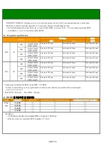
  Table1, Gas valve 2nd pressure each Model

          Unit   mmAq

MAX

MIN

MAX

MIN

MAX

MIN

MAX

MIN

  Table2,  Nozzle diameter each model and gas

             Unit   mm

LPG

Model

LNG

Model

LPG

LNG

Ø1.55Х13EA

Ø1.68Х15EA

Ø1.68Х17EA

Ø1.1Х15EA

16D

20D

16D

30D

GAS

Ø1.1Х17EA

Ø1.1Х13EA

Ø1.1Х10EA

Ø1.55Х10EA

20D

25D

30D

25D

3-6  Adjustment and gas Conversion             

DIP S/W

Potentiometer minimum

Potentiometer maximum

26페이지

Summary of Contents for eco condensing - 16D

Page 1: ...mbination boilers Technical information and Installation Servicing Instructions Model eco condensing 16D 18 6 kW eco condensing 20D 23 2 kW eco condensing 25D 29 1 kW eco condensing 30D 34 9 kW eco condensing Gas Boiler 1페이지 ...

Page 2: ...5 5 Adjustment and gas conversion 25 6 Direction for assembly 6 1 Disassembly 27 6 2 Part list 28 7 Maintenance guide 7 1 Main heat exchanger 29 7 2 Burner unit 30 7 3 Fan unit 31 7 4 controller unit 31 7 5 Temperature sensor 32 7 6 Over heating sensor 32 7 7 Gas valve 32 7 8 Circulation pump 33 7 9 3Way valve 33 7 10 Others 33 8 Function of the controller 8 1 Main controller 34 8 2 Function 35 9 ...

Page 3: ... Durable condensate neutralization device works the strong acidity PH3 4 of condensate down the normal water PH6 4 Safety low voltage and powerful TURBO FAN Powerful turbo fan offer the steady combustion system without interruption from the changeable wind 4 Durable condensing heat exchanger Aluminum and Stainless steel material of main heat exchanger extends its life cycle And double collecting c...

Page 4: ...efficiently and silently even on the low pressured gas supply 11 Thoughtful consideration on safety and convenience It is equipped with gas leakage detector water hammer protector and water over pressure reducer as special safety devices Additionally there are test operation function precise water temperature setting function and reservation function as useful and convenient features Stainless ste...

Page 5: ...66 39 85 9 Fixing bolt BEND 39 85 9 1 Product description Flue MODEL POWER SOURCE 507 x 310 x 788 220 240 V 50Hz DIMENSION Wx Dx H INSTALLATION TYPE FUEL TYPE HEATING AREA AL 1 st Heat Exchanger AL 2 nd Heat Exchanger CU Heat Exchanger Air Pressure Switch Turbo Fan PCB Syphon Gas Valve Circulation Pump DHW Heat Exchanger Pressure Gauge Auto Air Vent 3 Way Valve Igniter Expansion Tank Temperature s...

Page 6: ...2 Installation 2 1 Appliance dimension and required specification 6페이지 ...

Page 7: ...fore installing Boiler 4 he boiler should be installed onto the incombustible surface 5 Please avoid the wet place and hermetically sealed location The boiler can be installed on any suitable internal wall suitable sound proofing may be required when installing onto a stud partition wall Provision must be made to allow for the correct routing of the flue and setting of the terminal to allow the sa...

Page 8: ...t with or close to inflammable material and must not pass through building structures or walls made of inflammable material When replacing an old appliance the flue system must be changed MAX Length MIN 150 Assemble with packing without 100 150 8페이지 ...

Page 9: ...ve a flat roof to which people has access then a suitable stainless steel terminal guard must be fitted The minimum acceptable spacing from the terminal to obstructions and ventilation openings are specified in Fig X 2 3 2 Installing flue Connecting COAXIAL FLUE Connecting ASSEMBLING the socket of inlet and outlet flue 1 Join the flue socket on flue outlet 2 After sealing the top of boiler and soc...

Page 10: ...ORTANT If the boiler is not fitted immediately after the flue System temporary precautions must be taken to prevent rain entry into the room of installation Any precautionary measures must be removed prior to commissioning the boiler Flue Dimensions The standard horizontal telescopic flue kit allows for lengths between 315mm and 500mm from elbow to terminal Fig 13 The maximum permissible equivalen...

Page 11: ...Fig 16 NOTE The outlet must be positioned so that any condensate plume is directed away from adjacent surfaces There must be a constant fall along the entire of the flue system from the back to boiler 4 It is possible to reduce or increase with the addition of extensions the length of either or both 60 100 concentric and 60Φ exhaust 5 Standard concentric flue extension kits may be added between th...

Page 12: ...w 3 Locate the flue elbow on the adaptor at the top of the boiler Set the elbow to required orientation Fig 41 NOTE The flue elbow is angled at 93 degrees to ensure a fall back the boiler 4 Measure the distance from the outside wall face to the elbow This dimension will be known as X 5 If the distance from the flue elbow to the outside face of the wall X in is less than 250mm the Connection Assemb...

Page 13: ...ptor and flue 12 Ensure that the terminal is positioned with the slots to the bottom IMPORTANT It is essential that the flue terminal is fitted as shown to ensure correct boiler operation and prevent water entering the flue 13 Make good between the wall and air duct outside the building 14 Fit the flue trim inquired and if necessary fit a terminal guard see Section 8 8 8 9 CONCENTRIC VERTICAL FLUE...

Page 14: ... From a surface or boundary line facing a terminal K From a terminal facing a terminal Horizontal flue From a terminal facing a terminal Vertical flue L From an opening in carport e g door window into the dwelling M Vertically from a terminal on the same wall N Horizontally from a terminal on the same wall R From adjacent wall to flue vertical only S From an adjacent opening window vertical only T...

Page 15: ...e system must be taken into consideration Their equivalent lengths are Concentric Pipes Twin Flue Pipe 130 bend 0 5 meters 135 bend 0 25 meters 93 bend 1 0 meters 91 5 bend 0 50 meters The elbow supplied with the standard horizontal telescopic flue kit is not included any equivalent length calculations 20 meters Vertical Concentric Vertical Twin Pipe 15 meters 10 meters 15페이지 ...

Page 16: ...2 1 0 m 1 m 5 sub total fittings pipes Length Value 0 5 m 1 0 m 2 Equivalent N of AIR DUCT fittings pipes 0 5 m FLUE DUCT 0 25 m 0 5 m 5 5 0 m 5 0 m 2 Equivalent Length Air Duct 6 5 m Equivalent N of sub total Length Value 1 m 0 25 m Equivalent Length Air Duct 6 5 m 2 0 5 m 16페이지 ...

Page 17: ...r 1000mm 5111087 F Flue Bend pair 90 5111072 G Flue Bend 2 pair 135 5111086 J Vertrical Flue Boiler Adaptor Kit 5111079 H Vertrical Flue Adaptor 5111084 W Pipe Support pair 80mm 5111081 Y Flue TERMINATION Kit horixontal termination 80mm 5130172 Z Single Terminal 80mm 5131791 Q Adaptor 60 80 5121792 T Pitched Roof Terminal 25 45 5106164 FLUE GROUP G Flue System 80 125mm diamter A4 Horizontal Flue K...

Page 18: ...pe pressure Therefore if over it should install the pressure reducing valve for inlet water pipe additionally If over pressure of inlet water it may cause bursting pipes of house or boiler inside and stopping hot water from boiler 2 4 Piping Boiler Cool water INLET Pressure reducing valve Cool water valve join Nitrogen tank Heating pipe Distributor Cold water inlet pipe Hot water supply pipe Bath ...

Page 19: ...using to feed the boiler is suitable because if it is insufficient the power may be reduced causing inconvenience for the user 2 Water connection 1 The illustration shows the connections for the water and gas attachments of the boiler See valves configuration 2 Check that the maximum water mains pressure does not exceed 3bar if it does a pressure reducing valve must be installed 3 For measuring of...

Page 20: ...nless steel 4 Check the water level and fill the water to safety level of neutralization tank by opening make up water valve Caution Before the start of operation after installation or long stop open and close the air pulling valve on the top of main heat exchanger and keep the safety water level of the neutralization tank Warning When shortage of water in tank it may cause the danger due to the r...

Page 21: ... comply with the regulation 3 If this appliance is not earthed by power plug ensure to earth separately by minimum 30cm inserted in the ground Note not to connect gas pipe telephone wire and lightning conductor rod in order to avoid any accident from lightning surge or the gas accident 4 Make sure that the socket outlet is apart by over 30 cm from the appliance 5 The power outlet has to have at le...

Page 22: ... off valve installed between gas pipe and boiler Does check the gas leakage of each connecting points Does insulate each pipes properly to protect in winter season Does check the leakage of the exhaust gag from the flue Does check the voltage and hertz AC 220 230V 50Hz before of plugging on Does locate the middle on off valve for water inlet pipe Does check the classification of the supplied gas t...

Page 23: ...omplete 5 Check the exhaust fume See section Complete 8 Spin the pump Complete 11 Balance the central heating circuit Complete 14 Make a combustion rate with once pressing on RESET button during 5 sec Complete 1 Check the electrical supply Complete 4 Measure the gas inlet Complete 7 Check the hydraulic tightness Complete 10 Adapt the regulation at the heating instation Complete 13 Adjust DHW flow ...

Page 24: ... To ensure correct readings the boiler must have reached maximum operating temperature Testing the boiler before thermal equilibrium has been attained will give incorrect readings NOTE If you have only 1 probe measure separately air and flue gas close the test point not in use 7 6 1 1 4 2 9 3 5 11 15 1 1 1 1 18 12 2 20 16 22 23 24 25 8 2 2 1 AL Heat Exchanger 2 CU Heat Exchanger 3 Limit Switch 4 H...

Page 25: ...lumns Digital Digital manometer to burner test point with silicone tube B downstream of the gas valve Operate boiler for central heating After setting DIP S W Nr 8 to the ON position adjust potentiometer C on the main board at the minimum Adjust minimum pressure by rotating screw D clockwise to reduce pressure and anticlockwise to increase pressure After adjusting the minimum pressure turn OFF pos...

Page 26: ...PG and vice versa the main burner injectors must be replaced Minimum and maximum pressure must then be adjusted on the gas valve Table1 Gas valve 2nd pressure each Model Unit mmAq MAX MIN MAX MIN MAX MIN MAX MIN Table2 Nozzle diameter each model and gas Unit mm LPG Model LNG Model LPG LNG Ø1 55Х13EA Ø1 68Х15EA Ø1 68Х17EA Ø1 1Х15EA 16D 20D 16D 30D GAS Ø1 1Х17EA Ø1 1Х13EA Ø1 1Х10EA Ø1 55Х10EA 20D 25...

Page 27: ...4 Direction for assembly 4 1 Part exploded view 27페이지 ...

Page 28: ...water sensor 30 DHW Heat Exchanger 31 Safety valve 32 Air Water Separator 33 3Way valve 34 Ball valve 35 DHW Outlet Temp Sensor 36 DHW Inlet Temp Sensor 37 DHW Inlet Pipe 38 Main Controller 39 Power cord 40 Room Controller 41 DHW Flow Sensor 42 43 44 S121100062 중화장치 소음기 가스 혼합기 S114100086 S261200006 S323100039 S311200015 판형 열교환기 안 전 변 Neutralizing agent 실내온도조절기 유량센서 콘 트 롤 전원코드 통합블럭 운 모 포토센서 S132100...

Page 29: ...exchanger 4 screws on top and bottom with screw driver Ignition transformer Ignition rod Photo sensor 1 With spanner unfasten the nut of the gas pipe 1 Unscrew the cover of main heat exchanger 2 Open it 1 Tool On reverse order assemble the parts and boiler 5 1 Main heat exchanger Warning Carefully assemble the cover and nut to seal the parts If fail to seal there may occur the accident of gas leak...

Page 30: ... photo sensor from the heat exchanger exchanger from the case 1 Unscrew the burner from main heat exchanger 1 Dismantle the burner from main heat exchanger by driver downward 2 Remove the bracket from main heat exchanger Warning If fail to seal them firmly it may cause the failure of the correct combustion 2 To assemble burner keep the above orders as reverse and check the sealing gasket and brack...

Page 31: ... front cover with screw driver 4 And then dismantle the main heat exchanger after unscrewing 5 4 Controller unit 1 Plug off 1 Pull the controller unit 3 With screw driver unscrew 2 points on top and 2 Separate all connector carefully bottom sticking the controller unit to case 5 3 Fan unit Tool 1 1 1 3 1 1 2 31페이지 ...

Page 32: ...heat exchanger 3 Turn and pull out the temperature sensor from main heat exchanger right top side 5 7 Gas valve 1 Close all valves on the bottom of boiler 1 Pull out all the connectors from gas valve 2 With spanner unwind the nut of gas pipe between 2 With screw driver remove the screws from the burner and gas valve bottom of boiler and disassemble the adaptor from gas valve 3 Separate the gas val...

Page 33: ...e bottom 3 Separate water filter and circulation pump 5 9 3way valve 1 With spanner unwind the nut 1 Disjoin the clip of Central heat water pipe and 3 way 2 Pull up and down and separate the 3 way valve valve ass y from the extension tank 2 Pull and separate 3 way valve 5 10 others 1 Disassembling the safety valve and 1 Disassembling air vent 2 Disassembling the pressure gage drain hose 1 1 1 1 2 ...

Page 34: ...ot water outlet sensor 7 DHW Flow Sensor 8 Cold water inlet sensor 9 Thermal sensor of extension tank 10 Water temperature sensor 11 Overheat Burning infrared rays Room temp 11 12 13 1 4 15 16 17 18 19 20 21 9 8 6 1 2 3 4 5 7 10 No Name 12 Gas valve 13 Ignition transformer 14 Auto water inlet valve 15 Circulation Pump 16 3way valve 17 POWER 18 Heating Water Level Sensor 19 10P Connecter 20 MOD 21 ...

Page 35: ...none about below 5 about below 8 Pretection from cold winter Circulation pump starts on Repeat 10minutes on 30 seconds off Automatically return normal operation after over 10 over 50 of water temp sensor 5 minites operation Circulation pump starts on Automatically return normal operation Circulation pump stop after P T operate after over 18 of temperature sensor and Setting TEMP means the room tar...

Page 36: ...der to protect the burn from the initial failure POST PURGE TIME 10 sec 1sec After stopping the burn the fan will operate for some seconds to emit the exhausted gas from boiler Ⅰ Normal operation time chart Safety cut off time chart 6sec 1sec If the photo detector fails to sense the flame after steps of fan start prepurge preignition fuel supply it cut off the fuel supply for safety combustion If ...

Page 37: ...on specification Ⅰ For AC fan it will work on 220V within the allowable voltage 10 Ⅱ Proportional Control On comparing the target water temp with the current water temp it control the pressure of gas inlet and fan speed for the effective combustion It means if big difference it burn on the high gas pressure Gas valve FAN remark Model Forced ignition 1set operation FAN output value RPM mm2O output ...

Page 38: ...sic rpm 660 rpm basic rpm 660 rpm basic rpm 540 rpm basic rpm 660 rpm basic rpm 660 rpm basic rpm 540 rpm basic rpm 660 rpm basic rpm 660 rpm Proportional controlled fan RPM basic RPM 720 RPM In order to control the gas valve proportionally it works by max and min repeatedly before of starting the ignition transformer Max RPM 7200 rpm Min RPM 960 rpm 6 MODEL별 적용부품 및 일반기능 Type Close type RPM mm2O 2...

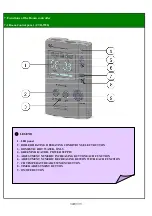
Page 39: ... BOILER HEATING OPERATING CONDITION SELECT BUTTON 3 DOMESTIC HOT WATER ONLY 4 GREEN INDICATOR POWER SUPPLY 5 ADJUSTMENT NUMERIC INCREASING BUTTON EACH FUNCTION 6 ADJUSTMENT NUMERIC DECREASING BUTTON WITH EACH FUNCTION 7 CH TEMPERATURE ADJUSTMENT BUTTON 8 TIMER ADJUSTMENT BUTTON 9 ON OFF BUTTON 39페이지 ...

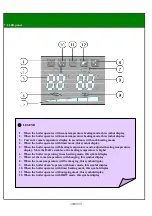
Page 40: ...ode adjusted heating temperature display More the BAR s numbers the heating temperature is higher 6 When the boiler is operating in each setting mode this symbol display 7 When set the room temperature will changing this symbol display 8 When the room temperature will be changing this symbol display 9 When the boiler doesn t operate with timer mode this symbol display 10 When the boiler operates w...

Page 41: ...ing until less than 1 minute for PCB defective 5 times repeat E 04 Interruption in heating temperature sensor Sensor connection defective sensor faulty E 14 Interruption in DHW outlet temperature sensor Sensor connection defective sensor faulty E 34 Interruption in DHW inlet temperature sensor Sensor connection defective sensor faulty E 05 Interruption safety high limit sensor wire PCB defective f...

Page 42: ... 7 34 9 30 000 Min working Pressure for DHW 0 2 2 9 Min working Flow Rate for DHW 1 60 0 42 Domestic Hot Water Output 18 6 16 000 23 2 20 000 29 1 25 000 Adjustable Temperature Heating 45 80 113 176 Total Volume Expansion Tank Expansion Tank Pre Charge 1 0 14 5 MaxHeating Temperature 85 185 Heating and Domestic Hot Water Production Air Closed Type Heating Water Circulation Method Purpose Heat Loss...

Page 43: ...10 Memo 43페이지 ...

Page 44: ...11 Warranty 44페이지 ...

Reviews: