- 32 -
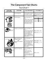
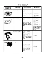
Test Chart 2
COMPONENT
ILLUSTRATION
COMPONENT
TEST PROCEDURE
TEST RESULTS
Coil Elements
Set the ohmmeter to
R x 1.
Connect the meter leads
to the element termi-
nals, and measure the
continuity.
8
"
Coil (2600W) =
22
Ω
±
5
Ω
6
"
Coil (1500W) =
38
Ω
±
5
Ω
Set the ohmmeter to
R x 1.
Connect the meter leads
to the element terminals,
and measure the conti-
nuity. NOTE: Halogen
tubes should show conti-
nuity.
Ceran Elements
9
"
Rad (2400W) =
22
Ω
±
5
Ω
7
"
Rad (1700W) =
32
Ω
±
5
Ω
6
"
Rad (1400W) =
39
Ω
±
5
Ω
7
"
Hal (1800W) = 0
Ω
Dual Oval (2500W Tot)
Hal Inner (1500W) = 0
Ω
Rad Outer (1000W) =
50
±
5
Ω
Convection Fan Motor
Set the ohmmeter to
R x 1.
Connect one of the
meter leads to circuit
board pin J1-1.
Connect the other meter
lead to circuit board pin
J1-6.
15
Ω
.
±
3
Ω
CONVECTION
FAN MOTOR
TERMINAL
TERMINAL
Cooling Fan Motor
Set the ohmmeter to
R x 10.
Connect one of the
meter leads to circuit
board pin J1-1.
Connect the other meter
lead to the yellow wire
marked “FAN” on the
cooling fan thermal
switch.
65
Ω
.
±
10
Ω
COOLING
FAN MOTOR
TERMINALS
ELEMENT
TERMINALS
SENSOR TERMINALS
Summary of Contents for KERC500B
Page 1: ...KITCHENAID ELECTRONIC RANGE CONTROLS B D LINE WALL OVENS JOB AID Part No 4317169 ...
Page 4: ... iv NOTES ...
Page 47: ... 43 NOTES ...
Page 93: ... 45 QUESTIONS ...

