- 31 -
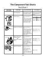
The Component Test Charts
COMPONENT
ILLUSTRATION
COMPONENT
TEST PROCEDURE
TEST RESULTS
Test all input and output
connections to board.
Refer to the error codes
on the previous two
pages.
L1
L2
H2
H1
P
P
L1
L2
H1
H2
Set the ohmmeter to
R x 1.
Connect the meter leads
to the switch terminals,
and measure the conti-
nuity when the switch is
turned ON and OFF.
Infinite Switches
Switch
ON
Switch
OFF
L1-P = 0
Ω
L1-P =
∞
Ω
L1-H1 = 0
Ω
L1-H1 =
∞
Ω
L2-H2 = 0
Ω
L2-H2 =
∞
Ω
Set the ohmmeter to
R x 1.
Connect the meter leads
to the thermostat termi-
nals, and measure the
continuity when the
switch is heated above
104˚F, and then cools to
below 104˚F.
Below 104˚F =
∞
Ω
.
TERMINALS
BAKE ELEMENT
SHUTDOWN SWITCH
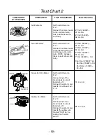
Below 395˚F =
∞
Ω
.
Above 104˚F = 0
Ω
.
Above 395˚F = 0
Ω
.
Bake & Broil Element
Shutdown Switch
OR
Bake Burner Shutdown
Switch
Set the ohmmeter to
R x 1.
Connect the meter leads
to the thermostat termi-
nals, and measure the
continuity when the
switch is heated above
395˚F, and then cools to
below 395˚F.
Door Latch Solenoid
Set the ohmmeter to
R x 10.
Connect one of the
meter leads to circuit
board pin J1-1.
Connect the other meter
lead to circuit board pin
J1-8.
55
Ω
.
±
10
Ω
CONTROL PANEL
SHUTDOWN SWITCH
&
COOLING FAN
THERMAL SWITCH
SOLENOID
TERMINALS
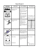
Electronics Board
Test Chart 1
Cooling Fan Thermostat
Summary of Contents for KERC500B
Page 1: ...KITCHENAID ELECTRONIC RANGE CONTROLS B D LINE WALL OVENS JOB AID Part No 4317169 ...
Page 4: ... iv NOTES ...
Page 47: ... 43 NOTES ...
Page 93: ... 45 QUESTIONS ...

