φ32
φ32
Socket head
cap screw[15]
Washer[18]
Cover[3]
Proximity switch[22]
Seat packing[8]
Lock bolt
Socket head cap screw[14]
Forward
Back
Stroke
Chuck close
(O.D. gripping)
Socket head cap screw[15]
Chuck open
(O.D. gripping)
Plston
Detectable Plate[11]
After securely tightening to the
piston.tighten the lock bolt
Coolant
Always clean so that the
chips are not clogged
Body[1]
Sheet packing[7]
Metal screen[6]
Sleeve body
Drain port
To the tank
for coolant
To the
hydraulic unit
DC24V
BK(Out put) OP2
BK(Out put) OP1
Type
Applicable cylinder
CSS10BN
CSS12BN
CSS15BN
S1036
S1246, S1246L
S1552, S1552L
Type
Applicable cylinder
CSS18BN
CSS20BN
CS-28SW
S1875, S1875L
S2091, S2091L
S2816
Type
BES M12MI-NSC20B-BV02
(BALLUFF)
Voltage
Leakage current
Operation style
24V DC
200mA or less
NPN
Type
BES M12MI-NSC20B-BV02
(BALLUFF)
OP2
+V
0V
OP1
BLACK
BROWN
BLUE
BLACK
BN(+) +V
Load
Load
BU(−) 0V
BN(+) +V
BU(−) 0V
17
18
Check the points specified below again and take measures.
7−1 In the case of malfunction
In the case of malfunction, contact the distributor where you purchased the product or our branch office listed on the
back cover.
7−2 Where to contact in the case of malfunction
7 . Malfunction and Countermeasures
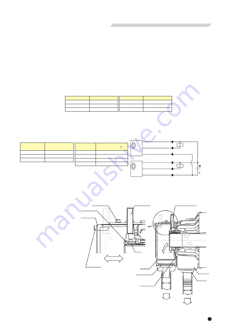
○The coolant collector is attached to the Kitagawa S type rotation hydraulic cylinder, and easily collects the coolant
flowing inside the draw pipe.
○To electrically check piston operation and for clamping/unclamping detection of a work, There are 2 proximity
switches attached to the coolant collector.
○The coolant collector is to be arranged separately from the cylinder, so designate the type specified below when
necessary.
○There are 2 proximity switches attached on the coolant collector, therefore, the cylinder operation can be checked.
8−1 Outline
8 . Coolant Collector
・If the chuck failed due to a seizure or breakage, remove the chuck from the machine, following the disassembly
steps in the chuck instruction manual, and then remove the cylinder by the reverse steps of "9. Attachment" after
page 21. When the jaws and covers cannot be removed due to a blockage of workpiece, do not disassemble
forcibly but please contact us or our agent.
・If these countermeasures do not correct the problem or improve the situation. Immediately stop using the
machine. Continuous use of a broken product or a defective product may cause a serious accident by the
cylinder or the work flying out.
・Only experienced and trained personnel should do repairs and fix malfunctions. Repair of a malfunction by a
person who has never received instruction from an experienced person, the distributor or our company may
cause a serious accident.
Table 4
8−2 Type and applicable cylinder
○The standard specification of the proximity switch is BES M12MI-NSC20B-BV02 (BALLUFF). Contact us if a
specification other than the standard one is necessary.
8−3 Specifications
○Insert a sheet packing between
the coolant collector main body
and the sleeve body at the
cylinder rear end, and attach
the coolant collector to the
cylinder rear end.
○After attaching the coolant
collector, attach the detectable
plate to the piston.
○To easily collect the coolant
flowing into the coolant
collector, provide appropriate
slope to the piping, so that the
coolant does not stagnate
inside the hose.
To check the flow, use a
transparent vinyl hose.
(Inside diameter φ32) (Fig. 6)
8−4 Attachment
Fig. 5
Table 5
Table 6
Table 7
Fig. 6
WARNING
Defective
Measures
Check that the hydraulic pressure is operating by the motion of the flexible hose, etc.
Check that there are no mistakes in piping.
Try operations when operation inability specified in the items of the trial operation.
Check that the pressure is as specified at the cylinder pipe inlet by attaching a pressure
gauge near the inlet of the cylinder.
Wearing of the O-ring inside is possible when the flow rate of the returning side pipe or
the drain is more than usual.
Check that the viscosity of the hydraulic oil is as designated.
Replenish the hydraulic oil inside the tank if it is low.
When the room temperature is high and the radiation effect of the tank is bad, control
the oil temperature using a cooler or a fan, etc.
Do not suck air.
Replenish the hydraulic oil inside the tank if it is low.
If a large amount of dirt is deposited inside the tank, or when the hydraulic oil is
deteriorated, the pump may be worn out abnormally, and it will be necessary to repair
the pump.
Provide a stream slope, without air pockets, and no back pressure must be applied.
Return the drainage onto the surface of the oil of the hydraulic unit .
Check that the air breather of the hydraulic unit is not clogged.
Piston
Operation
Inability
Cylinder
Thrust Force
Insufficiency
Temperature
Rise
Pump noise
Oil leakage
from labyrinth
Summary of Contents for S1036
Page 31: ......


