C
Mass of the other parts
W
o
r
k
Stopper
Socket head
cap screw
A
B
External force
4 port 2 position switching valve
Cylinder
Manual switching
valve for inside
and outside
diameter gripping
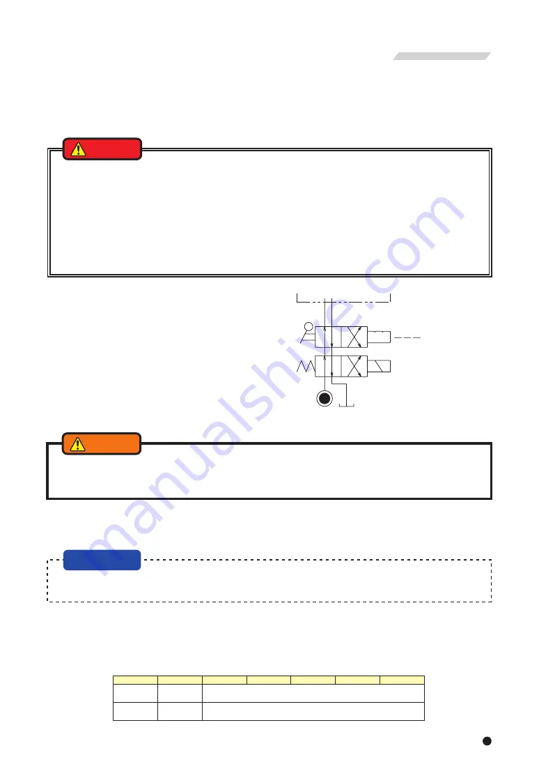
・Use the operation cylinder incorporated with a lock valve or relief valve to be prepared for blackout.
・Additionally, the solenoid valve is to be in a circuit to retain the gripping port position when no electric current is carried.
The switching of the cylinder is to be 4 port 2 position with electromagnetic valve, and design the hydraulic circuit
which grips the work in the state that the solenoid valve is degaussed.
If the circuit is designed in the opposite way, if there is a blackout, the work could be released and fly out.
・Provide a valve to switch over the inside and outside diameter gripping to prevent an operation mistake when
changing the gripping.
Additionally, when a solenoid valve is used as this switching valve, use a 4 port 2 position valve with a position
stopper that can retain the indicator circuit at the time of blackout.
・Select the operation equipment that matches the pipe diameter of the cylinder. The smaller the diameter is, the
larger the pipe resistance becomes and the lower the acting speed is.
Remarks 1) What is a lock valve ?
Valve equipped with a function to retain the
hydraulic pressure inside the cylinder
temporarily when the hydraulic pressure
suddenly drops due to blackout, malfunction
of the hydraulic pump, etc.
Remarks 2) What is a relief valve ?
Valve equipped with a function to prevent
breakage when the hydraulic oil filled inside
the cylinder caused a pressure increase due
to the volume change.
○Consider the hydraulic circuit design so that the operation is easy and no mistakes in operation occur.
Attempt failsafe for the circuit so as not to cause any accidents even in the case of blackout. (Fig. 19)
○It is incorporated with a lock mechanism to maintain the specified gripping force even if the supplied pressure
abnormally drops due to blackout or malfunction of the pressure resource while processing a work, however, it does
not function unless the following warnings are observed.
10 . About Hydraulic Circuit Design
<Installation>
The hydraulic pressure supply ports are port A (cylinder pushing side) and port B (cylinder pulling side) in Fig.20.
Though both ports A and B have two ports each, connect the pipes to one port respectively and plug the reminders. For
the size of each port, see Table 16.
Table 16
DANGER
Fig. 19
NOTICE
S2816
S2091(L)
S1875(L)
S1552(L)
Rc1/2
Rc1/2
S1246(L)
S1036
Rc3/8
Rc3/8
Type
A port
B port
28
27
9−6 Attachment of parts other than parts manufactured by
Kitagawa Iron Works
Table 15
Refer to following pages when you attach the other than parts manufactured by Kitagawa Iron Works (a stopper to
shorten stroke or spindle work stop, etc.) to the cylinder. (Refer to Fig.18 and Table 15)
Fig. 18
Table 14
※Since the material of the cylinder is aluminum, it is 80% of the tightening
torque to the bolt size specified for the hydraulic chuck of our company.
・If there is unbalance of the parts to attach, vibrations are generated and cause oil leakage which could result in a
fire. and if the hydraulic oil leaks, the gripping force of the chuck will lower and the work may fly out, which is
dangerous.
・External force is excessive, the bolt will break, which is dangerous as the cylinder or work will fly out.
・We will not assume responsibility for injury, death, damage, or loss caused by usage of parts not manufactured
by Kitagawa Iron Works. Additionally, if parts other than genuine parts manufactured by Kitagawa Iron Works are
used, this guarantee will be completely invalid.
・The personnel who designed those parts must judge whether they are safe for the usage conditions.
・The dimensions and value specified in this manual do not guarantee that the cylinder or the parts other than parts
manufactured by Kitagawa Iron Works will not break under every usage condition.
WARNING
Bolt size
Tightening torque
M10
M12
M16
58 N・m
85 N・m
200 N・m
Type
S1036
S1246
S1552
S1875
S2091
S2816
S1246L
S1552L
S1875L
S2091L
Run-out
(mm)
0.02
0.02
0.02
0.02
0.02
0.02
0.02
0.02
0.02
0.02
External force
(kN)
2.0
2.0
2.5
2.5
1.5
2.5
2.0
2.5
2.5
1.5
Mass
(kg)
2
2
3
3
3
3
2
3
3
3
Screw depth
(mm)
11
9
9
9
14
13
9
9
9
14
Bolt size
6-M5
6-M6
6-M6
6-M6
6-M6
6-M6
6-M6
6-M6
6-M6
6-M6
C
(mm)
4
4
4
4
4
4
4
4
4
4
φB
(mm)
55
64
73
98
108
188
64
73
98
108
φA (H7)
(mm)
64
76
85
108
120
200
76
85
108
120
Note) External force is a value at static load.
・To avoid serious injury from flying work, use the throttle valve to keep the surge pressure low. Operation failure
and cylinder breakage may occur if a reducing valve used for the hydraulic pressure setting fails to respond to
pressure adjustment and results in excessive surge pressure.
WARNING
Remark ) What is a surge pressure ?
Pressure produced by a change in velocity of the moving stream that result from activating a hydraulic pump,
operation of a solenoid valve.
Summary of Contents for S1036
Page 31: ......


