24
After installation make sure that the device is
properly mounted and it is impossible to
detach it from the mounting surface.
Opening of the boiler door or flue
leakiness
cannot
expose
the
controller directly to hot gases and
fire from the fireplace.
12.4
Connecting electrical system
Before unscrewing the terminal
cover of the controller, it is
necessary to disconnect the power
supply.
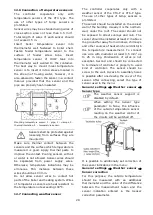
Controller terminals cover.
The controller is designed to be fed with 230
VAC, 50 Hz voltage. The electrical system
should be:
•
three core, with protective wire PE,
•
in accordance with applicable regulations,
•
equipped with a residual current
protection device (RCD) with inrush
current I
Δn≤30mA, protecting against
the effects of electric shock and limiting
damage to the controller, including
protection against fire.
After deactivating the controller,
there still can be a dangerous
voltage on the connections. Before
starting assembly works it is
obligatory
to
disconnect
the
electrical power and make sure
that there is no danger electrical
power on claps and wires.
Connection cables should not have contact
with surfaces which temperature exceeds
cables nominal operating temperature.
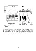
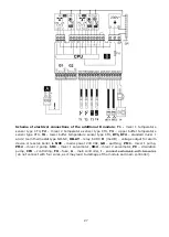
Terminals L, N, 1-11 are designed to connect
devices supplied by the mains 230 VAC
voltage. Terminals 12
–
25, G2 are designed
to work with low-voltage devices (<15 VDC).
Connection of the 230 VAC mains
voltage to terminals 12-25 or to
transmission terminal G1 results
in the controller damage and
poses a threat of electrocution.
For safety reasons, the controller
must be absolutely connected to
the 230 VAC power grid, with the
sequence of connecting the phase
(L) and neutral (N) wires. Make
sure that the L and N conductors
are not exchanged within the
building's electrical system, e.g. in
an electrical socket or in an
electrical socket junction box.
Protection lead of the power supply cable and
protection leads of connected devices should
be connected to the (7) protective strip
placed inside the casing of the regulator
marked with
.
Electrical cables should be
isolated from hot parts of the
boiler, especially from flues.
The wires should be secured against pulling
out using cable clamps (1). Tighten the cable
clamp screws (2) with such force that the
mechanical stress on the wires does not
cause them to tear or loose from the
terminals.
Due to protection class IP20, all
cable clamps (1) must be fitted,
even when all clamps are not
needed.
Summary of Contents for ecoMAX360P1-C
Page 6: ...6 ...
Page 7: ...USER SETTINGS ecoMAX360P1 C ...
Page 18: ...18 ...
Page 19: ...19 INSTALLATION AND SERVICE SETTINGS ecoMAX360P1 C ...
Page 42: ...42 ...
Page 43: ...43 ...


