32
button can be pressed only after the boiler
water temperature drops.
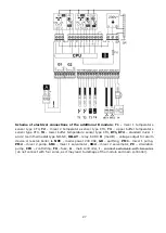
Resetting the STB safety temperature limiter: 1 -
protection nut, 2 - reset button.
Dangerous voltage exists at
terminals 1-2.
12.16
Thermal protection
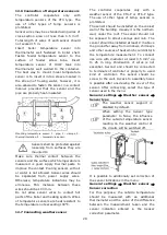
The controller equipped with additional
thermal protection (APT), type DZT-1. It cuts
off the fan and feeder power supply. Sensor
of the additional thermal protection, which
operates on low safe voltage, should be
placed in the thermometric pipe of the water
jacket. You should provide good thermal
contact of the DZT-1 sensor, and secure it
against coming loose from the measured
surface. If the boiler temperature exceeds
the DZT-1 sensor activation temperature
(85°C or 90°C±5 depending on the DZT
-10
type), the fan and feeder power supply is cut
off. The fan and feeder power supply will be
automatically restored after the boiler
temperature drops several degrees Celsius.
The thermal protection cannot
be
used
instead
of
the
mandatory
STB
safety
temperature limiter.
12.17
Connecting of room thermostat
•
Universal thermostat
The
controller,
on
terminals
19-20,
cooperates with a universal room thermostat
(NO-NC), when setting the parameter:
Service settings
→
Boiler settings
→
Thermostat select.
=
Universal
Shorting the thermostat contact causes
heating.
•
Wireless room thermostat/panel
Wireless radio connection of the eSTER_x40
room thermostat or eSTER_x80 room panel
requires connection to the ISM_xSMART
radio module controller, in accordance with
point 12.5 and pairing between the
thermostat / panel and the radio module.
A description of the pairing and operation of
the wireless panel / thermostat can be found
in the manuals of these devices. For a
wireless thermostat / panel connection, set
the parameter:
Service settings
→
Boiler settings
→
Thermostat select.=
ecoSTER
The thermostat / room panel for the boiler
circuit can turn off the burner or turn off the
boiler pump, according to the settings in the
menu:
Service settings
→
Boiler settings
•
Wired room panel
The controller can be wired with the
ecoSTER200 or ecoSTER TOUCH room panel.
In this case, set the parameter:
Service settings
→
Boiler settings
→
Thermostat select. =
ecoSTER
a)
Four-wire connection.
Allowed only when connecting the
ecoSTER200 room panel.
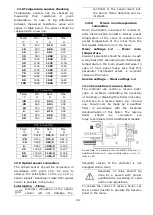
Four-wire connection of the executive module with the
ecoSTER200 room panel.
Summary of Contents for ecoMAX360P1-C
Page 6: ...6 ...
Page 7: ...USER SETTINGS ecoMAX360P1 C ...
Page 18: ...18 ...
Page 19: ...19 INSTALLATION AND SERVICE SETTINGS ecoMAX360P1 C ...
Page 42: ...42 ...
Page 43: ...43 ...


