KINTECH ENGINEERING
ORBIT 360 | USER GUIDE
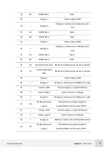
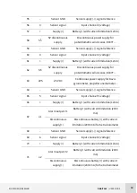
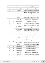
44
89
o6
Alarm output #6
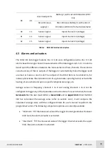
B) with current limitation (2000
mA)
Discontinuous
)
Discontinuous b) with current
limitation (2000 mA) for Setra barometer
90
13
Sensor signal
Input channel 13 (voltage)
91
14
Sensor signal
Input channel 14 (voltage)
92
15
Sensor signal
Input channel 15 (voltage)
Table 2.
Orbit 360 terminal description
4.5
Alarms and actuators
The Orbit 360 data logger features 18 x 8 = 144 user-configurable alarms: 16 x 8 = 128
alarms based on single channel measurements of the data logger and 2 x 8 = 16 alarms
based upon the difference between the measurements of two channels. These alarms
can actuate any of the six outputs of the logger or automatically make the logger send
an email or make an alarm call. The outputs of the Orbit 360 can be utilized to, for
instance, deactivate the ventilation unit of a pyranometer upon high wind, activate the
heating of an anemometer upon a specific temperature range, etc.
Average values on frequency channels 1 to 8 and analog channels 1 to 8 can be
configured to trigger any of the 8 possible alarm actuations. For each channel, there are
two levels that the user must define: a lower limit and an upper limit. Once the Orbit
360 has calculated the average value (refer to section 4.2.2), it will compare the
calculated average value with the configured limits for each channel to perform the
programmed action. The following comparison options are currently available:
“Minimum”
if the measured value of the logger channel goes below the lower
limit level, the alarm/actuator is activated.
“Maximum”
if the measured value of the logger channel exceeds the upper
limit, the alarm/actuator is activated.


