KINTECH ENGINEERING
ORBIT 360 | USER GUIDE
50
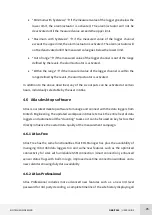
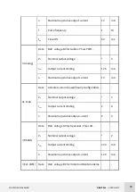
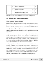
V
o
Nominal output voltage
*
V
I
lim
Output current limiting
2.5
A
I
o
Maximum operative output current
2.5
A
*The output voltage will be equal to the voltage on the power supply terminals.
5.4
Technical specifications: input channels
5.4.1
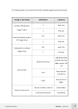
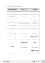
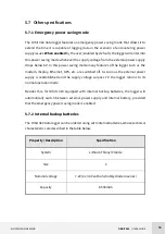
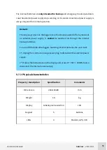
Frequency / Counters channels
The Orbit 360 data logger frequency inputs channels capture and count every single
pulse present on its terminals. As the capture is attended through an interrupt service
routine, all pulses are captured and processed at any moment, regardless the task the
data logger is performing when the pulse arrives.
The number of physical channels available on each logger depends on the commercial
model chosen.
Every time the voltage on the frequency input channel, passes from below to above a
specific voltage level the data logger will capture the event as a pulse. Therefore, the
compatible signals can be a voltage square wave, sinusoidal or any other waveform that
has a high and low level above and below the threshold voltage. The threshold voltage
level for each channel is preprogrammed in the data logger according to the type of
sensor configured for that frequency channel on the data logger settings.
The frequency input channels are provided with varistor and diode overvoltage
protection, for short duration electrostatic discharges typically arriving from lightning
strikes. The effectiveness of the protection is extremely sensitive to the grounding
conditions (refer to sections 4.3.5 and 6.3). Following the protections, there is a second-
order low-pass filter with 3KHz cut-off frequency. The filters should attenuate noise
interference like those coming from electrical lines, RF antennas or other instruments.
It is critical to use shielded cables with the shield properly connected at one end.

