


11
03
Installation
Manual 4804 Rev E p/n 004804 0000
rates shown in
are
on the order of +10% with no sealant recovery
system, +25% to -50% with partial sealant recovery
systems. Full recovery systems have an optional
sealant circulating pump that may be necessary if
sustained operation above 400 Torr (533.28 mbar)
is anticipated.
SEALANT FLOW CONTROL
The types of devices used to control the sealant
flow depend on the sealant arrangement used, the
size of the pump, and individual preference. A low-
cost constant flow control device is generally used
for no recovery systems and for the supply branch
of partial recovery systems. Another method is
to install an upstream adjusting valve and an
intermediate pressure gauge. The valve can then
be adjusted to obtain a specified pressure, thus
producing the desired sealing flow rate and gas
inlet pressure. The latter procedure generally
provides the most economical sealing flow rate.
To achieve greater water conservation, the partial
recovery system can be used with an optional
water miser and the fresh water flow adjusted for
the highest operating temperature compatible with
the process.
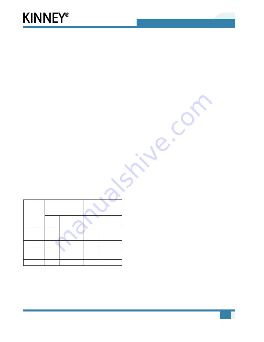
Table 3-1 – Recommended Flow Controllers
Model
Sealant Flow
(orifice) controller
“A”
Shaft Seal Flow
(orifice) controller
“B”
NPT
GPM / L/min
NPT
GPM / L/min
KLRC-40
3/4"
5 / 19
3/8"
1/4 / 1
KLRC-75
3/4"
5 / 19
3/8"
1/4 / 1
KLRC-125
3/4"
7 / 27
3/8"
1/4 / 1
KLRC-200
1"
8 / 30
3/8"
1/4 / 1
KLRC-300
1"
12 / 46
3/8"
1/4 / 1
KLRC-525
1"
20 / 76
3/8"
1/2 / 2
KLRC-950 1-1/4"
25 / 95
3/8"
1/2 / 2
With a partial recovery system an optional sealant
flow control valve actuated by sealant discharge
temperature may be used to automatically reduce
fresh sealant flow when water temperatures are
low. This will reduce sealant consumption below
normal partial recovery flow rates. Fresh sealant
flow may also be increased to achieve desired
cooling and improve pump performance. In order to
reduce sealant water consumption in once-through
and partial recovery systems, a solenoid valve may
be fitted to the sealant supply line. This valve will
be integral with pump start/stop operation, thereby
opening the sealant supply line during pump start-up.
An automatic sealant makeup valve and level
switch will allow makeup water to be added to
maintain a predetermined level in the discharge
separator. Conversely, if the system has a large
amount of condensables and is adding liquid to
the gas/liquid discharge separator, the above valve
and switch can be used to activate a drain valve
to lower the liquid level in the discharge gas/liquid
separator.
When sustained operation is required above
400 Torr (533.28 mbar), or with rapid cycling
on small volumes, an optional circulating pump
is recommended. This will also apply for long
roughing cycles. Also, if the pump RPM is below
standard (1,750 RPM), the use of a circulating
pump should be considered. High sealant viscosity,
and low specific heat and density, may require a
greater sealant recirculation rate and the use of a
circulating pump.
COOLING PIPING FOR
MECHANICAL SEALS
Sealant must be piped to the mechanical seals in
order to keep the seal faces cooled and lubricated.
The seals will fail if a suitable flow of sealant is not
supplied. The sealant must be clean and free of
particulates. Dirt or grit will cause the seal faces
to wear and fail prematurely. Connect the sealant
piping to the seals as shown in
through
Note that the connections to the pump are different
for KLRC-40 and -75 compared to KLRC-125 to
-950.


