background image


Revision: 4                                 Date: 18 Jun 2020                                                                    Page 20 of 28 


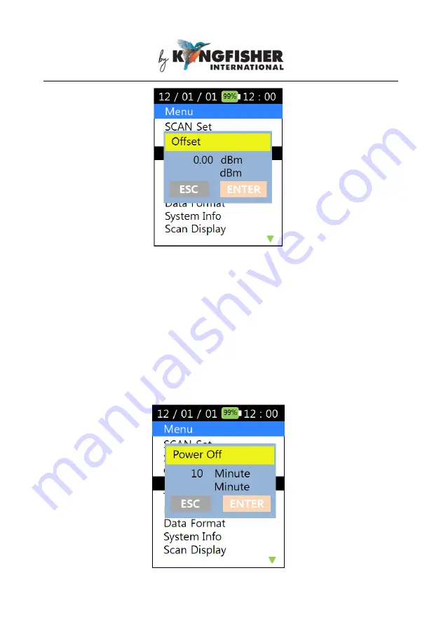
6.10.3 Auto Power Off 

Use  this  option  to  program  the  time  elapsed  before  the  instrument  is 

automatically  switched  off  after  the  last  key-press.    See  picture  below  for 
this option’s user interface. 

Press  [ENTER],  use  numerical  keys  to  input  a  time  (between  5  ~  600 

minutes) and press [ENTER] again to save setting or press [ESC] to return 

to Menu Option list without saving. 


Summary of Contents for KI6501

Page 1: ...pair of the equipment This Kingfisher International product is guaranteed against defective components and workmanship for a period of 1 year from the date of delivery unless specifically stated in th...

Page 2: ...tions of instrument keys 8 6 2 Switching Instrument ON OFF 9 6 3 PM Power Meter Mode 10 6 4 CWDM Mode 12 6 5 SCAN Mode 12 6 6 Measurement unit dB dBm selection 13 6 7 Graphical Display Mode 14 6 8 Sav...

Page 3: ...nagement Software enables stored test data to be downloaded to PC Applications of KI6501 CWDM Power Meter include the following Wavelength selective Power Meter for systems with CWDM channel spacing Q...

Page 4: ...librated wavelengths Larger sunlight readable backlit colour display Simultaneous 9 wavelengths loss display Tabular and graphical display modes Internal memory for 1000 test records Test data transfe...

Page 5: ...Display 2 8 Colour LCD with backlight Display unit dBm dB Display resolution 0 01 dB Memory 1000 records of 18 tests in internal memory PC interface Data transfer via USB Battery type Built in rechar...

Page 6: ...isture gets into the instrument remove the batteries and dry it out carefully for at least one hour before using it again Storage The equipment can be stored at the specified temperatures and relative...

Page 7: ...Revision 4 Date 18 Jun 2020 Page 7 of 28 5 Instrument Layout Instrument keys Optical Connector Charging status LED Mini USB connector Color LCD Display...

Page 8: ...er Meter Mode CWDM Scan present dBm in single wavelength display mode SCAN Scan present dBm in multiple wavelength display mode dB dBm Toggle between measurement units Graph Present scanned dBm wavele...

Page 9: ...n see pictures below for instrument displays When the instrument is switched ON its LCD backlight can be toggled ON or OFF by pressing Backlight Backlight will turn off automatically approx 30 seconds...

Page 10: ...is operation mode the instrument automatically scans the optical input and displays the wavelength along with its corresponding measured power value which has been detected with the highest level of p...

Page 11: ...e power values of the wavelengths available at the optical input See picture below for user interface of this mode In PM auto Mode press PM once to switch to PM Manual Mode Use to select the desired w...

Page 12: ...Use to display the power values of other wavelengths scanned at the optical input 6 5 SCAN Mode When SCAN is pressed the wavelengths and their corresponding power values scanned at the optical input w...

Page 13: ...Page 13 of 28 6 6 Measurement unit dB dBm selection Press dB dBm to toggle between the measurements units of dB and dBm in PM Power Meter Modes The displayed power will be become 0 00 dB when dB dBm...

Page 14: ...le Press Graph again will switch the display to the multiple wavelength format shown in example of section 6 5 6 8 Saving Scanned Data in Instrument s Memory In SCAN Mode press Save to save the scanne...

Page 15: ...ieving Data Save in Instrument Press Recall and the user interface below will be displayed Use to highlight the desired file in which data was saved followed by pressing ENTER The data will be retriev...

Page 16: ...retrieved data in graphical or tabular multiple wavelength format 6 10 Instrument Setup options Press Menu to display the available instrument setup options in the Menu Option List Pictures below show...

Page 17: ...strument scans its optical input for all 18 wavelengths despite of the wavelengths selected in Select Lambda option see section 6 10 2 When All Scan is OFF Selected is ON The instrument scans its opti...

Page 18: ...o select the wavelength s press ENTER on the display below Use to highlight the desired wavelengths from the available 18 wavelengths displayed in 2 pages Press ENTER to toggle ON select or OFF unsele...

Page 19: ...offset by the value pre programmed in this option See picture below for this option s user interface Press ENTER use the numerical keys to input the desired offset values between 25 99 25 99 dBm Use o...

Page 20: ...elapsed before the instrument is automatically switched off after the last key press See picture below for this option s user interface Press ENTER use numerical keys to input a time between 5 600 min...

Page 21: ...o Menu Option list without saving 6 10 5 Data Delete option Use this option to delete selected test data records from instrument s internal memory See picture below for this option s user interface Us...

Page 22: ...o delete all test record files saved in instrument s internal memory See picture below for user interface of this option Press ENTER to confirm that All data will be deleted or press ESC to return to...

Page 23: ...y work only with Scan Mode section 6 5 optical input scan result in the following options Display the scanned wavelengths detected with power values only OR Display all the wavelengths selected for sc...

Page 24: ...ode option This option provides an alternative method to that in section 6 3 of programming PM Modes see section 6 4 to operate in Auto or Manual condition See picture below for the user interface Use...

Page 25: ...hreshold level which is visible when the scanned data is presented on graphical format Use the numerical keys to enter a new valid threshold value 40dBm 10 dBm and use for or sign selection Press ENTE...

Page 26: ...26 of 28 6 10 11 Graph Color This option provides choices of displaying graphical test result in different colour format Previously programmed threshold Reprogrammed threshold Previously programmed t...

Page 27: ...ng of Instrument Link the mini USB connector on instrument see section 5 Instrument Layout to a PC s USB port or a USB charger using the provided USB cable The Charging Status LED see section 5 Instru...

Page 28: ...free of dust or other contaminant by cleaning them regularly 2 Do not use unclean or nonstandard adapters 3 Change adapter carefully if necessary and keep any spare adapter in dirt dust free environme...

Reviews: