background image

Page 26 of 56

King Pigeon Hi-Tech. Co., Ltd.

Ver 2.3

Industrial Ethernet Remote I/O Module

IoT Data Acquisition Module

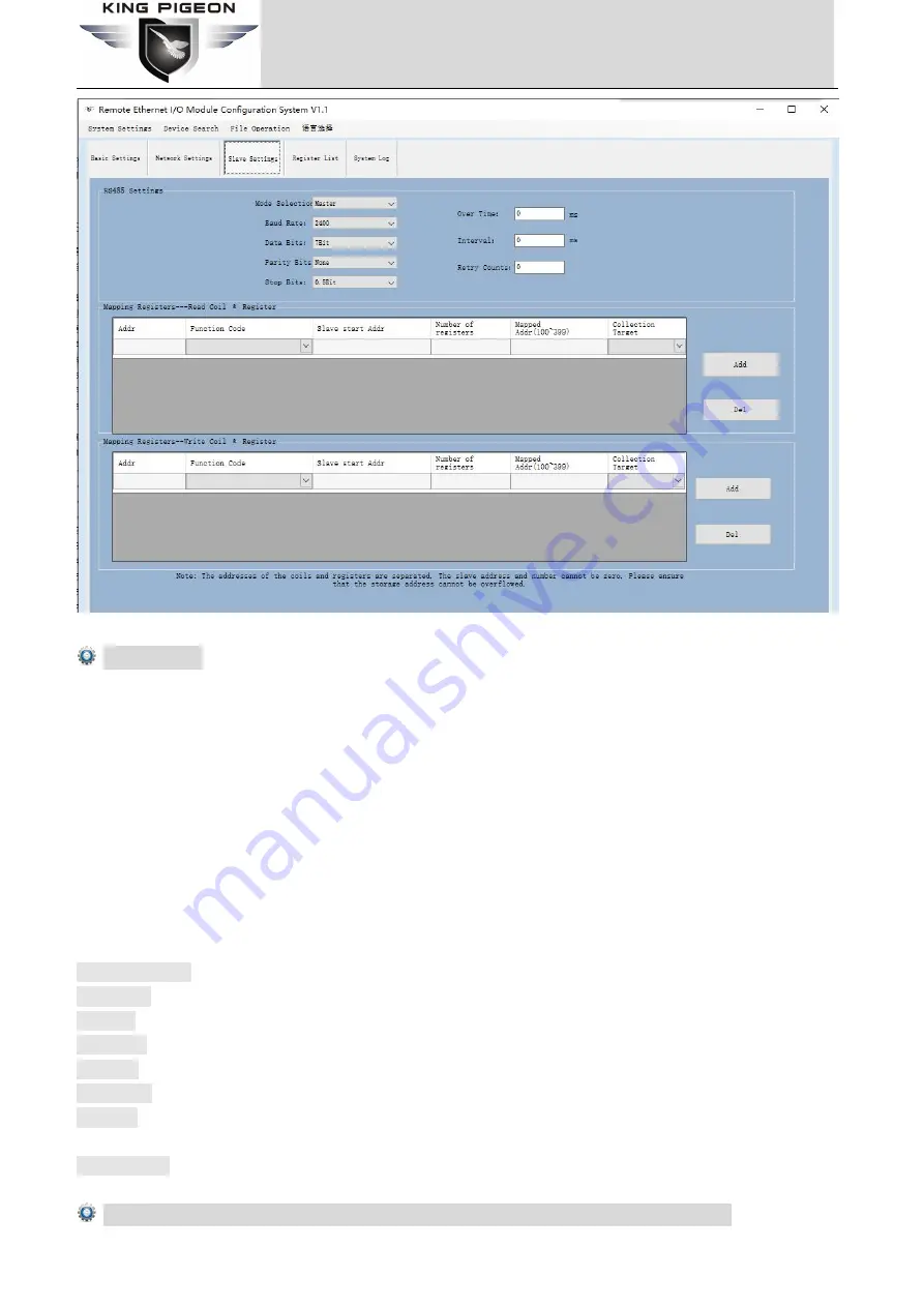
RS485 Settings

If the slave is only provides RS-232 interface, please use the RS-232/RS-485 converter connected to the 485
network. It is strongly recommended to use the isolated RS485 converter to improve system reliability. In a BUS, all
of the equipment

data A + should be connected together, and data B- should be connected together, cannot be

reversed, RS485 signal to the GND terminal should be shorted together, and connect to the module

s ground only.

RS-485 network generally allows up to 32 nodes in parallel devices, more than 32 systems need to use RS485
repeater to expand. RS-485 communication line should be STP(shielded twisted pair), the shield should be
single-ended ground; RS485 communication distance can be up to 1200 meters, when a bus connected to a lot of
RS485 devices, or use high baud rate higher communication distance Will be correspondingly shortened
accordingly, then you can use RS485 repeater to expand. RS-485 network has a variety of topology, the general use
of linear connection, that is, start from near to far, connecting devices to the master one by one. In the far end can
be connected to 120 ~ 300

Ω

/ 0.25 watts of terminal matching resistance (depending on the communication

quality to determine).

Mode Selection :

Master or Slave optional.

Baud rate :

2400,4800,9600,14400,19200,38400,57600,115200,128000 optional.

Data Bit:

7, 8 bit.

Parity Bit:

None, Even and Odd optional.

Stop Bit:

0.5Bit, 1Bit, 1.5Bit, and 2Bit optional.

Over time:

Wait for the command reply time, the next command will be sent after timeout, default 200ms

Interval:

Polling time, each command sending interval time, default is 200ms; please increase the time

appropriately when there are too many slaves.

Retry counts:

command reply timeout retry times, default is 3 times.

Mapping Registers--Read Coil & Registers: Mapping registers between the slaves and module

Summary of Contents for M T Series

Page 1: ...g I O or Instrument Max 700KHz High Speed Pulse Counter Max 300KHz High Speed Pulse Output MxxT Series User Manual Ver 2 3 Date Issued 2020 11 08 King Pigeon Hi Tech Co Ltd www IOT Solution com Industrial Ethernet Remote I O Module ...

Page 2: ...2V M420T 1 RJ45 1 RS485 16 DO 1 DC 110mA 12V Special instructions for ordering 1 If the model provides digital input the DIN default type wet contact optional dry contact The input type cannot be changed after manufacturer delivered The DIN1 default is high speed count mode it can be changed to low speed count mode by open the shell and change the internal jumper If require dry contact input pleas...

Page 3: ... 7 7 System Log 29 8 Modbus Protocol 30 8 1Introduction to Modbus Register Address 30 8 1 1 Read Input Coil Function Code 2 Read Coil 30 8 1 2 Read and Write Holding Coil 31 8 1 3 Read Input Register 32 8 1 4 Read and Write Holding Register 34 8 1 5 Mapping Register Transit BIT Register Address 36 8 1 6 Mapping Register Transit 16 Bit Register Address 36 8 2Example of reading and writing registers...

Page 4: ...t waiting then can get a quick response to meet the industrial timely requirements The MxxxT Ethernet Remote I O module provides different I O ports for variety applications Includes optical isolated digital inputs compatibles dry contact and wet contact supports max 700KHz high speed pulse counter digital outputs supports 10Hz 300Khz high speed pulse output or relay outputs isolated 12bits analog...

Page 5: ...y and special filtering strategy to ensure its reliability The MxxxT Ethernet Remote I O module can work at wide working voltage range the range is 12 36VDC with anti reverse protection design Also it provides 1channel 12 36VDC power output for external device to save wiring cost 2 Standard Packing List Ethernet Remote I O Module X 1 Card type Manual X 1 35mm Standard DIN rail fixed Bracket 1 Note...

Page 6: ...upports PT100 and PT1000 resistance sensor compatible 2 or 3 wires High sampling frequency and special filtering strategy to ensure reliability 1 RS485 Serial port supports Modbus RTU Master Slave can extend I O modules Supports register mapping function and extend I O inquiry strategy Supports TCP Client and TCP Server supports max 5 TCP Client connections Provides 1 channel VDC power source outp...

Page 7: ...ctly otherwise must connect external relay I O Mode Sink or Pulse Output Pulse Output Frequency 10Hz 300KHz Only the 1st Channel is Sink type can be used as high speed pulse output Over Voltage Protection 50V DC Over Temperature Shutdown 175 C typical 150 C min Load Current Max 500 mA per channel Digital sampling frequency 500Hz Analog Input Type mA V Resolution 12 bits input impedance Voltage typ...

Page 8: ...e TCP IP TCP Connection Can be TCP client and server As TCP server support max 5 TCP client connection Serial Port RS485 MODBUS RTU Master or Slave Protection 15KV ESD Protection Modbus Slave address 1 247 Polling Frequency Default is 50mS range 30 65535mS Baud Rate 2400 4800 9600 19200 38400 57600 115200 128000Bps Mapping registers Bit registers 300 16 Bit register 300 Total 600 mapping registers...

Page 9: ... of 56 King Pigeon Hi Tech Co Ltd Ver 2 3 Industrial Ethernet Remote I O Module IoT Data Acquisition Module 5 Physical Layout and Installation Diagram 5 1 Physical Layout 35mm Standard DIN rail fixed Bracket ...

Page 10: ...cks while sending data on RS485 Serial port Digital input status indicator turn on or input high level or will close Digital Output status indicator turn on or output high level or will close 5 3 Interface Instructions for installation See below interface definition please connect the correct wires Interface Definition Instruction DC in 9 36V DC9 36V positive input 1A for power on the Unit If need...

Page 11: ...alog Input AINx The x channel Analog input positive GND Analog input negative Analog Output AOx The x channel Analog output positive GND Analog output negative RTD Input RTDx The x channel Resistance Thermal input positive RTDx Resistance Thermal input negative COM Resistance Thermal input COM port 5 4 Typically Wiring Instruction Safety ground The grounding wire helps prevent the effects of elect...

Page 12: ...Ver 2 3 Industrial Ethernet Remote I O Module IoT Data Acquisition Module DI Internal interface principle block diagram DI DO DIN1 DIN 16 1 16 digital input COM Digital input common DO1 DO1 6 1 16 digital sink output COM Digital output common ...

Page 13: ...Page 13 of 56 King Pigeon Hi Tech Co Ltd Ver 2 3 Industrial Ethernet Remote I O Module IoT Data Acquisition Module DI Wiring dry contact DI Wiring NPN sensor DI wiring PNP sensor ...

Page 14: ...Page 14 of 56 King Pigeon Hi Tech Co Ltd Ver 2 3 Industrial Ethernet Remote I O Module IoT Data Acquisition Module DO Internal interface principle block diagram ...

Page 15: ...ease reference above mentioned wiring instruction If the sensor near the module and the wire resistance is small can be ignored can be used 2 wire wiring if the distance is far and the wire resistance affect the value should be used 3 wire way connection RTD AI AO PT1 PT8 1st 8th PT100 PT1000 input positive PT1 PT8 1st 8th PT100 PT1000 input negative GND PT100 PT1000 input ground AI1 AI8 The 1st 8...

Page 16: ... AI Block diagram of internal interface principle Analog input type selection On the left side of the device each AI input channel can choose the input type by itself The three switches include 1 4 20mA 0 20mA 2 0 5V 3 0 10V The user needs to select the correct type according to the output type of the transmitter When selecting please turn the switch to the corresponding position ...

Page 17: ...i Tech Co Ltd Ver 2 3 Industrial Ethernet Remote I O Module IoT Data Acquisition Module and at the same time select the corresponding type on the configuration software The labels are as follows AI wiring 2 wire AI Wiring 3 wire ...

Page 18: ...Page 18 of 56 King Pigeon Hi Tech Co Ltd Ver 2 3 Industrial Ethernet Remote I O Module IoT Data Acquisition Module AO Block diagram of internal interface principle AO wiring ...

Page 19: ...Page 19 of 56 King Pigeon Hi Tech Co Ltd Ver 2 3 Industrial Ethernet Remote I O Module IoT Data Acquisition Module RS485 RS485 Wiring RS485 A RS485 Data A B RS485 Data B GND RS485 Data Ground ...

Page 20: ...ange to low speed pulse count mode by open the shell and change the JP2 JP3 s jump Caps to the right side2PINs see below pictures High speed mode Short circuit the upside 2 pins of JP2 JP3 s with Caps Low speed mode Short circuit the downside 2 pins of JP2 JP3 s with Caps Ethernet Indicator light Status Description Link indicator yellow Always bright Connection established Flashing Transferring da...

Page 21: ...ttings Operation The MxxxT Ethernet Remote I O module provides a standard Ethernet RJ45 interface through the direct line connect to the router switches HUB and other interconnect switching equipment or through the cross line connect to PC and other terminal devices The user can program parameters firmware upgrades and debugging through the WEB configuration interface In the actual use the Master ...

Page 22: ...the device password After modification you need to log in with the new password Save Data Save the parameter configuration to the device Loading Data Read the parameter configuration of the device Please read the current configuration before setting the parameters Time MAC address Click this item to read and modify the device time and MAC address restart to take effect after the MAC address is mod...

Page 23: ...e mode the default is that the maximum high speed pulse frequency is 700KHz and the maximum optional low speed pulse frequency is 10KHz DIN2 DIN12 can be used as low speed pulse counters the anti shake time can be set from 1 to 2000ms the default is 1ms and the corresponding pulse frequency is up to 1KHz DIN Input Status The state of the digital input When the state of the digital input is closed ...

Page 24: ...tomatically obtains the IP address in the LAN Only when the router in the LAN allows the dynamic allocation of IP addresses can be used User Specifies the IP Address Tick it stands for the user setup a fixed IP address for the module IP Address Gateway Netmask Primary DNS Secondary DNS Only can be set After choose User specifies the IP address Modbus TCP listening port 1 65535 default is 502 liste...

Page 25: ...opic name used by MQTT to publish messages The topic name is used to identify which information channel the payload data should be published to The topic name in the published message cannot contain wildcards Timing report time MQTT data timing release interval time MQTT Device ID The client identifier used in the MQTT connection message The server uses the client identifier to identify the client...

Page 26: ... to a lot of RS485 devices or use high baud rate higher communication distance Will be correspondingly shortened accordingly then you can use RS485 repeater to expand RS 485 network has a variety of topology the general use of linear connection that is start from near to far connecting devices to the master one by one In the far end can be connected to 120 300Ω 0 25 watts of terminal matching resi...

Page 27: ...bus slaves automatically by the corresponding Function codes according to the mapped registers Slave address slave device ID range 1 247 Function code Sets the type of action host to slave Including 05 15 write holding coil and 06 16 write holding register where the value of the holding coil is automatically allocated to the mapping storage area of the relay bit register and the value of the holdi...

Page 28: ...2 3 Industrial Ethernet Remote I O Module IoT Data Acquisition Module 32 bit takes 2 16 bit address 64 bit takes 4 16 bit address The module will automatically assign and stored them according to the coil or register set in Mapping Registers page ...

Page 29: ...oot Factory data restart nth boot Server mode connection request allow connection Server mode connection request exceeding the number of connections forbidden to connect Server mode close connection received Server mode no data for a long time close the connection Client mode successful connection to the server Client mode the server closes the connection Client mode no data for 10 minutes disconn...

Page 30: ...icate with the host The above applications can not be used as RS485 master and RS485 slave at the same time other applications can be supported at the same time The device s register address Modbus function code data type purpose and precautions are described in the following table Modbus TCP and RTU protocols are very similar Just add a MBAP header to the RTU protocol and remove the two byte CRC ...

Page 31: ...egisters are empty 8 1 2 Read and Write Holding Coil Function Code 1 Read Coil Function Code 5 Write Single Coil Function Code 15 Write multi Coils Read and Write Holding Coil Function Code 1 Function Code Function Code 15 Channel Modbus register address Decimal PLC or configuration use address Decimal Data Type Description DO1 0 00001 Bit DO1 Value Read Write 0 Open 1 Close DO2 1 00002 Bit DO2 Va...

Page 32: ...1 Low 30002 Low AIN2 0 High 30003 High 32 Bit Int ABCD AIN2 Value Read Only Real value Current value stored in register 100 1 Low 30004 Low AIN3 0 High 30005 High 32 Bit Int ABCD AIN3 Value Read Only Real value Current value stored in register 100 1 Low 30006 Low AIN4 0 High 30007 High 32 Bit Int ABCD AIN4 Value Read Only Real value Current value stored in register 100 1 Low 30008 Low AIN5 0 High ...

Page 33: ...16 Bit int RTD5 ADC Value Read Only Real value Current value stored in register 10 RTD 6 Temp 13 30014 16 Bit int RTD6 ADC Value Read Only Real value Current value stored in register 10 RTD 7 Temp 14 30015 16 Bit int RTD7 ADC Value Read Only Real value Current value stored in register 10 RTD 8 Temp 15 30016 16 Bit int RTD8 ADC Value Read Only Real value Current value stored in register 10 Reserved...

Page 34: ...Low 40005 Low DO1 Pulse Counter 5 High 40006 High 32 Bit unsigned ABCD Read Only automatically clear the value 6 Low 40007 Low DO1 Pulse Frequency 7 40008 16 Bit unsigned 1 30000 unit 10Hz means the DO1 output frequency range is 10Hz 300KHz Can be changed in operation DO1 Pulse Duty Ration 8 40009 16 Bit unsigned Range 10 90 stands for pulse Duty Ration is 10 90 Cannot be 0 and 100 Can be changed ...

Page 35: ... 24 low 40025 low DIN8 pulse count 25 High 40026 High 32 Bit unsigned ABCD The anti shake time can be set from 1 to 2000ms the default is 1ms and the corresponding pulse frequency is up to 1KHz 26 low 40027 low DIN9 pulse count 27 High 40028 High 32 Bit unsigned ABCD The anti shake time can be set from 1 to 2000ms the default is 1ms and the corresponding pulse frequency is up to 1KHz 28 low 40029 ...

Page 36: ...s Transit 16 Bit Register Address Function Code 3 Function Code 6 Function Code 16 Transit 16 Bit Register Address Data Type Description 100 399 16 Bit The 16 Bit type mapping registers in the internal memory of the module Used to store the serial port slave and TCP Client exchange data Notice Cannot read and write the same address 8 2Example of reading and writing registers For example MXXXT devi...

Page 37: ...CRC verify Device answer 01 02 02 03 90 B9 24 01 Device address 02 Query DIN status command 02 Return Byte Length 03 90 DIN status each bit represents a DIN status 0 represents open 1 represents closed the first byte 03H is converted into binary 0000 0011 corresponding to DIN1 DIN8 status from low to high the second byte 90H is converted into binary 1001 0000 corresponding to DIN8 DIN7 DIN6 DIN5 D...

Page 38: ...ess 01 Read DO function code 00 00 DO register starting address 00 10 Read 16 DO data continuously 3D C6 CRC verify Device answer 01 01 02 05 C3 FA FD 01 Device address 01 Read DO function code 02 Return Byte Length 05 C3 The returned DO status data each bit represents a DO status 0 represents open 1 represents closed the first byte 05H is converted into binary 0000 0101 corresponding to DO1 DO8 s...

Page 39: ... 01H Device according to the data Master send Function Code 1 05H Write a single holding coil use function code 05 DO register address 1 00 00H Register starting address Action performed 2 FF 00H This value is FF 00H or 00 00H FF 00H means control DO is closed 00 00H means control DO is open 16 CRC Verify 2 8C 3AH CRC0 CRC1 low byte in front high behind Example Control DO1 closed then Server send ...

Page 40: ...he data Master send Function Code 1 0FH Write multiple holding coils DO register starting address 2 00 00H Register starting address Number of bytes to be written 2 00 10H Indicates how many DOs have performed actions 16 CRC Verify 2 54 07H CRC0 CRC1 low byte in front high behind Example Simultaneously close the 16 DOs of this device then Server send 01 0F 00 00 00 10 02 55 AA 5D 0F 01 Device addr...

Page 41: ...esponds to 1 32 bit register Number of read registers 2 00 10H A total of 16 16 bit addresses are read and every 2 16 bit addresses are combined into a 32 bit address a total of 8 32 bit addresses that is the number of AIs is 8 16 CRC Verify 2 F1 C6H CRC0 CRC1 low byte in front high behind Receiver Return Data Format Content Bytes Data H HEX Description Device Address 1 01H 01H Device according to...

Page 42: ...00 00 19 C8 00 00 1E 14 00 00 22 60 Converted to true value 11 22 33 44 55 66 77 88 46 A0 CRC verify If you want to read certain input registers you only need to modify the register starting address and read register quantity and then recalculate the CRC check The returned data is analyzed as described above 8 2 5 Read local holding register Master Send Data Format Content Bytes Data H HEX Descrip...

Page 43: ... 00 00 00 00 00 00 65 C2 A8 00 00 00 00 00 00 00 00 00 00 00 00 00 00 00 00 00 77 9C 3D 00 05 16 15 00 00 00 04 00 00 00 05 00 00 00 06 00 00 00 07 00 00 00 08 00 00 00 09 00 00 00 0A 00 00 00 0B 00 00 00 0C F6 9D 01 Device address 03 Read holding register 46 Return the number of bytes 00 00 00 00 00 00 00 65 C2 A8 00 00 00 00 00 00 00 00 00 00 00 00 00 00 00 00 00 77 9C 3D 00 05 16 15 00 00 00 04...

Page 44: ...gister 1 Control a single holding register of this device Master Send Data Format Content Bytes Data H HEX Description Device Address 1 01H 01H Device Range 1 247 according to setting address Function Code 1 06H Write a single holding register use function code 06 DO register address 2 00 00H Register address Action performed 2 00 64H Set execution data as needed 16 CRC Verify 2 88 21H CRC0 CRC1 l...

Page 45: ...Code 1 10H Write multiple holding registers use function code 16 register starting address 2 00 00H Register starting address Control quantity 2 00 02H Control number Number of bytes to be written 1 04H 1 16 bit address needs to write 2 bytes 2 16 bit addresses need to write 4 bytes in total Data written 2 00 64 00 C8H Send to control execution data 16 CRC Verify 2 B3 E6H CRC0 CRC1 low byte in fro...

Page 46: ...ugh the Modbus protocol The correspondence between the mapped address and the slave device address needs to be configured through the Modbus master configuration page 8 3 1Read Bit mapping address data Master Send Data Format Content Bytes Data H HEX Description Device Address 1 01H 01H Device Range 1 247 according to setting address Function Code 1 01H Read the holding coil use the function code ...

Page 47: ... map address invalid invalid invalid invalid invalid invalid 109 108 value 0 0 0 0 0 0 0 1 Register map address 107 106 105 104 103 102 101 100 value 0 1 1 1 0 0 1 1 Address values higher than 10 bits are considered invalid values 5D 0C CRC verify 8 3 2Rewrite the bit mapping address data If you want to control the status of the holding coil connected to the slave you must configure the instructio...

Page 48: ...6 Bit CRC verify Device answer 01 05 00 64 FF 00 CD E5 01 Device address 05 Write a single holding coil 00 64 Mapped address to be written FF 00 written 1 8D EE 16 Bit CRC verify If you need to rewrite more than one please read Modbus protocol 15 function code 8 3 3Read 16 bit mapped address data Master Send Data Format Content Bytes Data H HEX Description Device Address 1 01H 01H Device according...

Page 49: ...g table Mapping register address 100 101 102 103 104 105 106 107 108 109 Hexadecim al value 00 14 00 1E 00 28 00 32 00 4B 00 41 00 0A 00 25 00 14 00 2A Decimal value 20 30 40 50 75 65 10 37 20 42 FB 34 CRC verify 8 3 4Write 16 bit mapped address data If you want to write the data of the connected slave you must configure the instruction mapping for adding slave 03 function code After the mapping a...

Page 50: ...mapped slave is a signed integer sorting AB rewrite the mapped address 20001 register to 100 then then Server send 01 06 00 65 00 64 98 3E 01 Device address 06 Write command function code 00 65 Write address 101 register value 00 64 Write the decimal value 100 98 3E CRC verify Device answer 01 06 00 65 00 64 98 3E 01 Device address 06 Write command function code 00 65 Write address 101 register va...

Page 51: ...Page 51 of 56 King Pigeon Hi Tech Co Ltd Ver 2 3 Industrial Ethernet Remote I O Module IoT Data Acquisition Module Http www iot solution com ...

Page 52: ...and some miniaturized devices The MQTT protocol runs on TCP IP or other network protocols and provides orderly lossless bidirectional connections Implementation principle of mqtt There are three kinds of identities in the MQTT protocol publisher Publish broker Broker server and subscriber Subscribe Among them the publisher and subscriber of the message are both clients the message broker is the se...

Page 53: ...Cloud 2 0 default is MQTTPW 9 Supplementary transmission check to enable supplementary transmission after enabling it the data during the offline period will be supplemented when reconnected to the cloud platform After the configuration is completed the client will initiate a connection to the server Connect the client sends a connect message request to the server Connack the server responds to a ...

Page 54: ... time stamp later connectionshave time stamp retransmit enable Historical data identification only for re transmission of historical data but not for real time data Note Read write identifier the character is flag followed by read write ID representing IO data point Data type and value it can be divided into 1 Switch data the character is switcher followed by 0 or 1 0 for open 1 for closed 2 Numer...

Page 55: ...D switcher 1 Data type and value flag DO1 Read write identification down down Platform downlink message identification Note Platform sensor ID character is sensorid followed by ID number ID is automatically generated by platform Data type and value it can be divided into 1 Switch data the character is switcher followed by 0 or 1 0 for open 1 for closed 2 Numerical data the character is value follo...

Page 56: ... DO1 Pulse output control DOCNT6 Value True value original value Expand slave I O data point read and write identification Data name Read write flag Data type Description bit data type COIL100 COIL399 Switcher According to the definition of slave data generally 0 means disconnection 1 means closing 16 bit data type REG100 REG399 Value The data type uploaded by MQTT is a 16 bit unsigned integer If ...

Reviews: