


7-8
06-235975-001
November 2002
Kidde Gemini II System
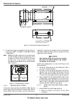
d.
Connect the battery. Close the AC circuit breaker
(i.e., power up the MCP).
e.
De-isolate the Release Output of the MCP via
menus.
The Kidde Gemini II MCP is now completely functional.
7-3.2.5
INSTALLING THE REMOTE HAZARD UNIT
(RHU)
1.
Install each RHU using the following steps:
a.
Make all conduit connections into the RHU enclo-
sure.
b.
Pull all system wiring through the installed conduit
into the enclosure.
c.
Mount the RHU Power Supply and PCB/Display
Assembly into the enclosure.
d.
Connect AC supply to RHU as described in Para-
graph 7-3.2.3. Close circuit breaker to supply AC
power. The only troubles should be a "Un-regis-
tered" trouble and a battery fault.
e.
If any other troubles are shown by the RHU, power
it down and make any alterations to the Device
hardware to remove any trouble/alarm events (e.g.,
fit any missing End-of-Line (EOL) Resistors).
f.
Open AC circuit breaker (i.e., power down the
RHU).
g.
Verify the integrity of the field wiring. Check for
grounds, shorts, opens, polarity and voltages.
h.
Complete all required system wiring connections
(except for the Release Circuits and Data Com-
munications) to screw terminals on the printed cir-
cuit board using Paragraph 7-3.3 and the system
installation drawings prepared by the supplier for
the specific installation.
i.
Close circuit breaker to supply AC power.
j.
Check that the newly connected field devices ap-
pear to be functioning. No new troubles should be
indicated by the RHU.
2.
Establish RS-485 Data Communication between the
RHU and the MCP by performing the following steps:
a.
Open the MCP and RHU AC circuit breakers (i.e.,
power down both units).
b.
Set the network address of the RHU (see Appen-
dix E for details) with the 3-position dip switch la-
beled SW2 (see Appendix E for the location of
SW2). Note that while each RHU must be assigned
a unique network address, an RHU and an RDU
may have the same address number.
c.
Connect the RS-485 Data Communication wiring
between the RHU and the MCP as described in
Paragraph 7-3.3.5. it is recommended that the
Remote units be connected one at a time and tested
thoroughly to verify proper communication before
the next unit is connected.
d.
Power-up the MCP (the display should read "Sys-
tem status normal").
e.
Connect battery to the RHU. (The RHU hardware
is designed so that the battery supply is physically
isolated. No power will be supplied from the bat-
tery to the RHU at this time.)
f.
Close the RHU AC circuit breaker. The RHU will
check its battery. If the battery passes the check,
the RHU will connect the battery in circuit.
g.
Reset the MCP. The MCP should establish com-
munication with the RHU. Both the MCP and the
RHU should show the trouble "Unregistered RHU."
h.
Enter the Configuration Parameters for the RHU
through the MCP Menu System as described in
Paragraph 7-4.
i.
At the MCP, register the RHU. When leaving
menus, the MCP should show "System status nor-
mal." The RHU will also show "System status nor-
mal."
3.
All field devices except the Releasing Devices are now
connected; continue with the following steps:
a.
Test the functionality of each input type field de-
vice and its correct interaction with the RHU (De-
tectors, Waterflow, Supervisory, Manual Release
and Abort). Events will be reported both at the RHU
and the MCP.
b.
Test the operation of the RHU Sounder outputs.
4.
If an Optional Relay Board is required, perform the fol-
lowing steps:
a.
Disconnect battery and open AC circuit breaker (i.e.,
power down RHU).
b.
Mount the Optional Relay Board using the hard-
ware provided (see Appendix E for location).
c.
Plug the connector into the 10-pin connector (J5,
see Appendix E).
d.
Connect field wiring to Optional Relay Board.
e.
Connect the battery. Close the AC circuit breaker
(i.e., power up the RHU). The MCP and RHU should
now show an Optional Relay Board trouble.
f.
At the MCP, configure the Optional Relay Board.
The MCP and RHU should again show "System
status normal."
g.
Test the operation of each field device attached to
the Optional Relay Board (i.e., activation on trouble,
supervisory etc.).
h.
Subject the RHU to a Walk Test as described in
Chapter 4.
firealarmresources.com


