


5-1
November 2002
06-235975-001
Kidde Gemini II System
CHAPTER 5
TROUBLESHOOTING
5-1
INTRODUCTION
This chapter contains maintenance and troubleshooting for
the Kidde Gemini II System.
5-2
ISOLATION: DISABLING INPUTS AND
OUTPUTS
The isolation feature permits the operator to isolate field
devices and output modules and is typically used to tem-
porarily isolate auxiliary devices during a system test. When
an input or output circuit is isolated, the unit will not react to
any events or troubles on that circuit, nor will it apply any
drive signals if the affected circuit is a release or indicating
circuit output. Isolation generates a Trouble event on the
display, logs the Trouble in the Event Log and sounds the
buzzer. Similarly, a de-isolation is also recorded and dis-
played. Events and troubles occurring on isolated circuits
are not entered into the Event Log.
The following circuits can be isolated:
•
Detector loops (initiating circuits 1 and 2)
•
Waterflow input
•
Manual release
•
Abort switch
•
Indicating output circuits 1 and 2
•
Alarm, Trouble, and Programmable relay outputs
•
Agent release outputs
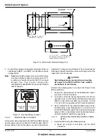
5-2.1
Procedure
1.
Press the down arrow to get to the Main Menu.
2.
Select Isolate.
3.
Select (De)Isolate RHUs or (De)Isolate RDUs.
Note:
Only registered units will be shown by the MCP.
4.
Select a unit. Use the up and down arrows to display
the desired unit. Then press ACCEPT.
5.
The first field will allow scrolling through the different
isolations available on the unit you selected. The
Change field allows toggling the displayed parameter
between isolated and de-isolated. Select OK to accept
changes. A confirmed or failed message will be gener-
ated.
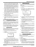
(De) Isolate MCP/RHU
(De) Isolate RDUs
(select unit)
Main Menu
Isolate
Detector inputs
Waterflow input
Sounder outputs
Supervisory input
Optional Relays
MCP alarm relay
Release outputs
MCP trouble relay
Abort switch
Manual release
MCP Prg Rel
Figure 5-1. Isolate Menu Structure
5-3
TROUBLESHOOTING EVENT MESSAGES
Ground FLT: This message will display when a short circuit
has occurred between part of a device (MCP/RHU) and
ground. This will be on some part of the internal or ex-
ternal wiring. The problem should be investigated and
corrected by a qualified Kidde service engineer.
NameTag FAIL: If the MCP menus are used to change the
name tag of a device (MCP or RHU), the new name
tag is transmitted to all RHUs and RDUs on the net-
work. This trouble event will occur if an RHU or RDU
fails to reply correctly to a message informing it of the
name change.
The problem can be corrected using the MCP menus.
The same device should be selected to have a change
of name tag. The required name tag should be set (if it
is not as required) and the name tag sent again. If the
RHU of RDU that failed to reply previously replies this
time then the "Name Tag FAIL" event will be removed.
Update FAIL: Whenever the MCP is reset, it sends mes-
sages to all RHUs and RDUs requesting an update of
all alarm and/or trouble events (this allows the MCP to
rebuild a "picture" of the System status). "Update FAIL"
will occur if an RHU or RDU fails to reply correctly to
the MCP request for an update.
firealarmresources.com


